Biomimetic Stimulating Array for Single Localized Stimulation in Visual Prosthesis
Villarreal DL*, Schroeder D, Krautschneider WH
Institute of Nano- and Medical Electronics Hamburg University of Technology, Hamburg, Germany.
*Corresponding Author
Diego Lujan Villarreal,
Institute of Nano- and Medical Electronics,
Hamburg University of Technology, Hamburg, 21073, Germany.
E-mail: diego.lujan@tuhh.de
Received: August 17, 2017; Accepted: October 06, 2017; Published: October 10, 2017
Citation:Villarreal DL, Schroeder D, Krautschneider WH. Biomimetic Stimulating Array for Single Localized Stimulation in Visual Prosthesis. Int J Comput Neural Eng. 2017;4(3):76-90. doi: dx.doi.org/10.19070/2572-7389-1700010
Copyright: Villarreal DL© 2017. This is an open-access article distributed under the terms of the Creative Commons Attribution License, which permits unrestricted use, distribution and reproduction in any medium, provided the original author and source are credited.
Abstract
Visual prostheses electrically stimulate nearby neurons to generate artificial vision in patients blinded by retinal degenerative diseases. Current prosthetic devices offer limited spatial resolution that results in unselective stimulation of ganglion cells and the generation of percepts with shapes other than a small spot of light. In this study, we introduce a theoretical approach to treat the biomimetic retinal electrode array. This array produces electrodes that are self-determined to adjust their spatial parameters for single localized stimulation. Electrode stimulation of the biomimetic electrode array was simulated in a 3D reconstruction of the retina and ganglionic layer at locations in the retina with high area cell density. We also simulated ganglion cell stimulation in the far periphery as the array could be relocated on the retina due to the natural movements of the eye. Single localized stimulation was achieved throughout the retinal regions near the fovea, which is required in humans for activities where visual detail is of primary importance and thus relevant for high resolution vision. Single-cell stimulation responses leveled off until 30° of eccentricity in average using the biomimetic array with large array area. That is, the biomimetic array can produce a stable stimulation of single cells and a broad field of view for a wide region of the retina. Lastly, we provide considerations for the biomimetic electrode array for practical applications. Together of being useful to improve single cell activation, the applicability of the biomimetic electrode array can yield strategies to increase the area of the array and produce a wide-ranging field of view.
2.Introduction
3.Background
3.1 Biomimetic Retinal Array
3.2 Single Localized Stimulation
4.Materials and Methods
4.1 Volume Region of Stimulation
4.2 Biomimetic Electrode Array Generation
4.3 Investigation of Electrode Stimulation
5.Results
6.Discussion
6.1 Mathematical Formulation of Single Cell Stimulation
6.2 How Biomimetic Array Changes Electrode Distribution?
6.3 Response of Biomimetic Array within 15° of Eccentricity
6.4 RGC Stimulation by Relocating the Biomimetic Array
6.5 RGC Stimulation in Arbitrary Locations on the Retina
6.6 Verification of the Biomimetic Electrode Array
6.7 Advantages of Biomimetic Electrode Array
6.8 Shortcomings of Biomimetic Electrode Array
6.9 Supporting Evidence
6.10 Considerations for practical applications
7. Conclusion
8. References
Keywords
Biomimetic Electrode Array; Prosthetic Vision; Retina Implant; Single-Cell Selectivity; 3D Retinal Reconstruction.
Introduction
Visual prostheses are designed to restore some vision to patients blinded by photoreceptor degenerative diseases, such as retinitis pigmentosa and age-related macular degeneration [1].
Recently, epi-and subretinal implants have been developed [1-10]. Humayun et al., [1-4], Mahadevappa et al., [5], Rizzo III et al., [6, 7], Klauke et al., [8], Eger et al., [9] and Keserü et al., [10] and recent clinical trials [11, 12] have confirmed the feasibility of producing perception of light in blind patients by electrically activating nearby retinal ganglion cells (RGCs).
Visual prostheses would ideally reproduce accurately natural spatiotemporal patterns of activity in RGCs with high resolution. This requires the capacity of each electrode to reach singlecell selectively. In other words, RGCs are tightly-packed in the ganglionic layer, mainly at the fovea. Unique characteristics of the visual space are sent to the brain via temporal patterns of activity in RGC types that are spatially mixed. RGCs that are close to each other frequently transmit very different signals [13].
The major problems with current visual prostheses are 1) the use of large electrodes with some fixed electrode spreading that misdirect the stimulus and create phosphenes with shapes other than a small spot of light and 2) the incapability to adapt electrode stimulation at locations with high RGC density. This presumably may be the cause of current clinical trials that revealed that patients do not obtain a complete visual scene composed of simultaneously presented percepts [11, 12].
Electrode array topology influences the shape and breadth of the phosphenes while the retina is electrically stimulated [14]. That is, by applying a given value of peak stimulus amplitude, the current spread varies according to the topology of the electrode array and the position of the active and ground electrodes. This could lead in changes in the area of stimulation, thereby causing the generation of phosphenes with shapes other than a small spot of light. Thus, electrode topology is fundamental to restrict the stimulus to the space required for producing round dot-like percepts. Experiments which were performed with different electrode topologies revealed dissimilar shapes of phosphenes e.g. elongated shapes [15, 16], triangles [17], lines/bars [16, 18], doughnut-shaped [3], complicated patterns [17] and round spots of light [3-5, 10, 16].
With that said, a novel theoretical approach must introduce an electrode array that can achieve small percepts and single localized stimulation at locations with high area density of RGCs. Thus, we introduce a theoretical approach to treat the biomimetic retinal electrode array. This biomimetic array produces electrodes that are independent to adjust the spacing between adjacent electrodes using a given area density of cells and ganglion layer thickness for the purpose of single cell stimulation.
To acquire a precise understanding of how electrodes activate RGCs, we shall consider first an accurate three-dimensional (3D) reconstruction of the retina, particularly in the ganglionic layer for an epiretinal design; second the activationof RGCs in a perspective three-dimensional region; third a mathematical approach for the activation of a single cell per stimulating electrode and fourth a theoretical approach to treat the biomimetic electrode array for the purpose of single localized stimulation.
The retina was reconstructed using a simulation framework built by integrating the relevant retinal interface elements and the dynamics of the ionic channels in the ganglion cell.
A three-dimensional reconstruction of the ganglion layer considered a realistic 1) density distribution of RGCs along the retina, 2) distribution of RGCs in the vertical section, 3) distribution of RGC size (diameter) and 4) variable ganglionic layer depth as a function of the eccentricity along the retina.
Recent retinal models [19-23] disregarded a representative three dimensional reconstruction of the ganglion layer for evaluating the direct stimulation of RGCs.
This present work examines the use of the biomimetic electrode array and its advantages for single localized stimulation at locations in the retina with high area RGC density. This is a requisite in visual prostheses because actions that require visual detail are processed within ±15° of eccentricity. We also inspect RGC stimulation in the periphery as the array could be relocated on the retina due to the natural movements of the eye.
Rodger et al., [24] designed, fabricated and implanted in animals a biomimetic retinal parylene C-based electrode array with 60 of 1024 75μm-diameter electrodes connected through dual-layer process. The biomimetic retinal array was able to stimulate tissue, elicit a response similar to the response generated from a light pulse and confirm excellent biostability.
Although that the biomimetic retinal array retained the spherical curvature of the retina and produced a complex biomimetic pattern that closely mirrored the area density distribution of RGCs in the human retina [25], the reasoning of how the biomimetic pattern is generated is incomplete.
RGCs found in the human ganglion cell layer [25] are not distributed along the border between the ganglion layer and the vitreous chamber but along the three-dimensional space of the ganglion layer that makes the volumetric density of cells.
Peak volumetric density is not in contact with the border between the ganglion layer and the vitreous chamber but leans toward the boundary between the ganglion layer and the inner nuclear layer [14].
These findings suggest that considering the area cell density as the only assumption could result in a clear misdirection of electrode stimulus to empty regions of cells, a misuse of electrodes and a misrepresentation of the nature of cell distribution.
As a result, an increase in stimulus amplitude is required to stimulate remote cells in the ganglion layer. This may lead the stimulus to reach undesirable localities where other cells could be stimulated, thereby reducing focal activation and greatly decreasing resolution, and to exceed electrochemical safety limits. Other issues neglected are 1) ganglion layer thickness varies as a function of the eccentricity, 2) single localized stimulation and 3) relatively large electrodes likely activate hundreds or thousands of cells over their area of stimulation [13].
Jepson et al., [26] reported that the five numerically dominant retinal ganglion cell types (i.e. ON and OFF midget, ON and OFF parasol, and small bistratified ganglion cells) have similar activation thresholds. In addition, single cells could be precisely activated without stimulating adjacent RGCs of the same type or other types.
The algorithm to find the volume of stimulation is shown in Figure 1(a). This volume is defined as a triggering boundary where the spreading current is sufficient to stimulate a single or nearby cells. That is, a cell located inside the volume is activated by the respective electrode. Otherwise, the cell is not activated by this electrode. Comsol Multiphysics and Matlab software were used for the volume of stimulation. The procedure is explained next.
The stimulation electrode arrangement consists of an active electrode surrounded by eight grounds. This array forms a 3 by 3 evenly distributed electrode arrangement, see Figure 1(b).
This stimulating array yields an advantage for single cell activation as the current density can be confined in a small region that surrounds the RGC. This results in a more controlled stimulation area [27].
Let us call a square area-element inside the stimulating electrode array with sizes labeled as d, see Figure 1(b), where d is the electrode pitch:
ρE is the electrode density.
In the course of this study, a total of 32 by 32 electrode array is considered. The control of selecting the role of electrodes to function as active or ground is also considered as seen in previous publications [27, 28]. Active electrodes can have their own time slot for stimulation [28]
The description to obtain the activation area and the volume region of stimulation was introduced in Villarreal DL et al., (2017) [14]. Here, the basic information is given to generate such volume of stimulation.
Consider an electrode array with electrodes having a size diameter and a local electrode density. The volume region of stimulation is generated by following the algorithm shown in Figure 1(a). The algorithm is created to restrict the spread of the stimulus to the space required for activation. This would result to a more precise region of stimulation and a high-resolution vision.
The inputs in the algorithm are the stimulating parameters (i.e. injected current, pulse duration, pulse shape and domain properties) and the geometric parameters (i.e. cell location, domain dimensions, proximity of cell to electrode and electrode distribution). A short introduction of each processing step is explained in sequential order based on its appearance.
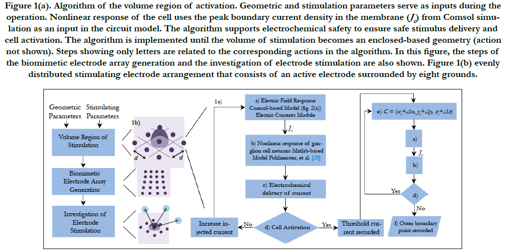
Figure 1(a). Algorithm of the volume region of activation. Geometric and stimulation parameters serve as inputs during the operation. Nonlinear response of the cell uses the peak boundary current density in the membrane (Jc) from Comsol simulation as an input in the circuit model. The algorithm supports electrochemical safety to ensure safe stimulus delivery and cell activation. The algorithm is implemented until the volume of stimulation becomes an enclosed-based geometry (action not shown). Steps showing only letters are related to the corresponding actions in the algorithm. In this figure, the steps of the biomimetic electrode array generation and the investigation of electrode stimulation are also shown. Figure 1(b) evenly distributed stimulating electrode arrangement that consists of an active electrode surrounded by eight grounds.
Electric Field Response: A 3D computational model of electrical stimulation was implemented in COMSOL Multiphysics software (COMSOL, AB., Sweden, Version 4.4). The model consists of one half of a sphere that represents a segment of the human eye, see Figure 2(a). The layers included in the simulation model are the polyimide carrier of the electrodes, vitreous medium, photoreceptor layer, ganglionic layer, ganglion cell soma and retinal pigment epithelium. This schematic representation of the retina is built to a greater degree of anatomical likeness than previously published works [19-23]. The sizes of each layer and electrical parameters are listed in Table 1 [19-23]. The geometric values of the retina are listed in Table 2.
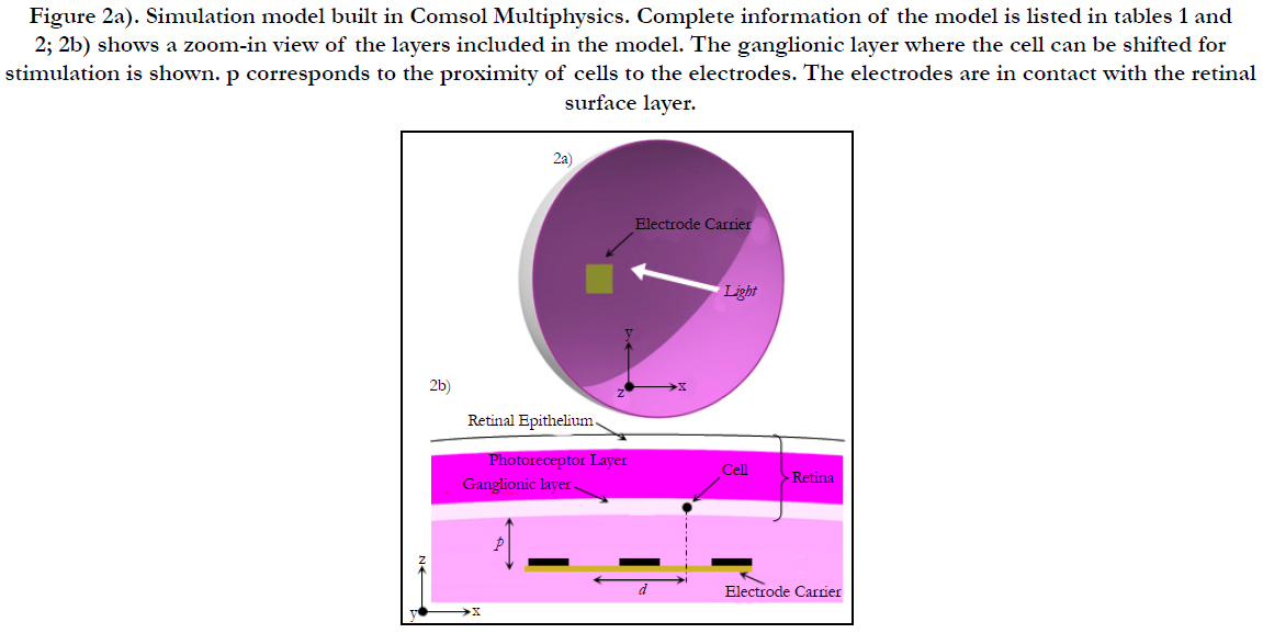
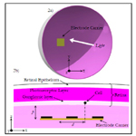
Figure 2a). Simulation model built in Comsol Multiphysics. Complete information of the model is listed in tables 1 and 2; 2b) shows a zoom-in view of the layers included in the model. The ganglionic layer where the cell can be shifted for stimulation is shown. p corresponds to the proximity of cells to the electrodes. The electrodes are in contact with the retinal surface layer.
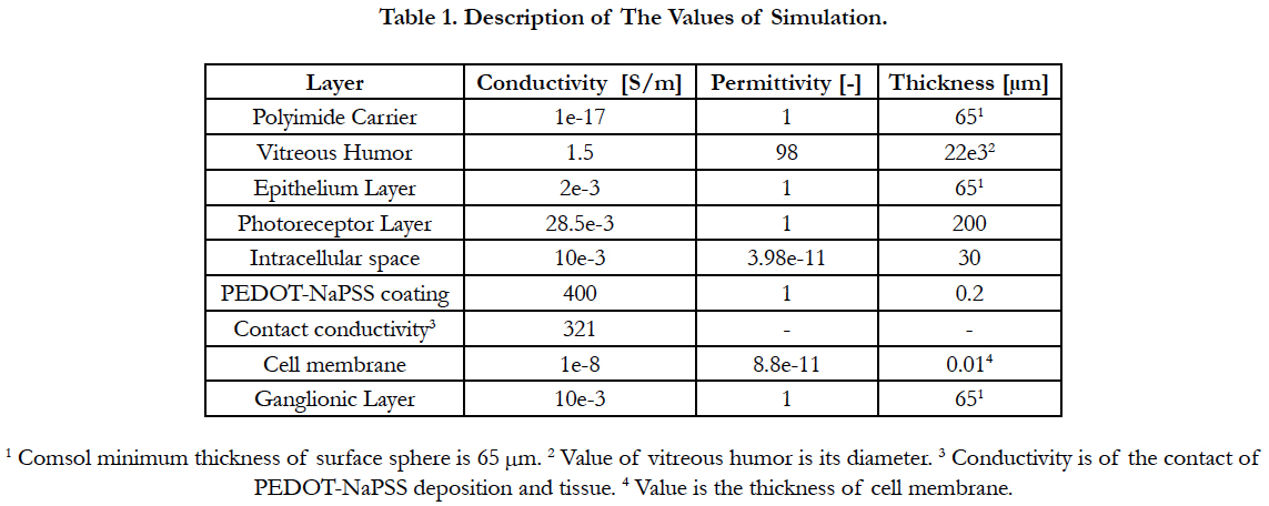

Table 1. Description of The Values of Simulation.
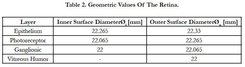
Table 2. Geometric Values Of The Retina.
The retinal network models (i.e. bipolar, horizontal and amacrine cells, ON- and OFF networks) are excluded because of severe rod and cone photoreceptor impairment that cannot drive synaptic connection started with a photocurrent input.
Biphasic pulses of uniform current are injected from the active to ground electrodes to drive single or nearby RGC stimulation. We extracted from Comsol the peak boundary current density in the membrane that encloses the ganglion cell. Other extracted data are the voltage across the electrodes and current delivered by the active electrode.
Nonlinear Response of Cell Neurons: We assumed that the peak boundary current density in the cell membrane serves as an input parameter in the circuit modelling of the RGC. The RGC circuit model was developed by Fohlmeister et al., [29]. The basic mathematical structure for voltage-gated ion channels was based on the Hodgkin and Huxley like equations [30]. Recent works used this modelling assumption for the mathematical model of Hodgkin and Huxley [31] and for the model of RGCs [14]. The parameters and equations that describe the dynamics of the ionic channels were kept as in the original model [29].
A Matlab (MathWorks, Inc., United States, Version 7.13) script implemented the ganglion cell circuit model and determined the stimulation of the RGC. That is, the threshold injected current required for the activation of a cell by means of extracellular stimulation must generate a voltage shift of around +30 mV in the cell membrane.
Electrochemical Safety: Safety, in terms of electrical performance, is mainly related to three factors: charge density injection level, heat generated at the tissue due to the power dissipation by the device, and the water-voltage window. That is, electrolysis of water, the formation of corrosion [32] and excessive tissue heating that harm cellular functions [33] must be avoided.
A Matlab script organized the extracted data of voltage across the electrodes and current delivered by the electrode and performed several tasks to obtain the heat dissipated by the device and charge density on the electrode. Local charge density was obtained by integrating the current delivered by the active electrode over time and dividing it by the electrode area.
Neural tissue heating from the retinal implant is calculated as seen in Villarreal DL et al., (2016) [27]. Initial value of body temperature of 37° degrees is assumed. A temperature changeof 1°C [34], a voltage window of 1.7V [35] and a charge density of 1 mC/cm2 [36] were assumed as safety limits for stimulation.
Cell Activation, Cell Shifting and Outer Point Recording: Comsol Multiphysics is used to stimulate a RGC by shifting it around the horizontal direction (x or y axis) and locating it at a distance of d/2 away from the active electrode, i.e. (xc, yc, zc), see step a) and Figure 2(b). The algorithm is iterated until the cellis stimulated. Electrochemical safety is checked first before the user can step forward, step c).
When steps until d) are successfully achieved, the threshold injected current across the electrodes can be recorded. Then, the cell can be shifted with distances (Δx, Δy , Δz) around the horizontal and vertical directions (z axis), see step e), to find places where this threshold current is not sufficient to stimulate. Then, the outer boundary point can be recorded, see step f). The algorithm is implemented until the volume is an enclosed geometry. This will eventually lead to the volume region of stimulation.
The procedure to obtain the activation area is similar to the volume region except that the cell is shifted only around the x and y directions to mark the places of stimulation. This will lead to the area of activation. This activation area bounded by the volume of stimulation is defined as a triggering boundary where the spreading current is sufficient to stimulate cells.
Thus, this volume can be related to the visual sensations represented as a phosphene [14]. In this regard, section Discussion - Supporting Evidence lists the supporting evidence. For more information regarding the activation area and the volume of stimulation, see [14].
The spatial information of the biomimetic electrode array was found using a 3D reconstruction of the ganglionic layer that was designed in Matlab for epiretinal stimulation. This reconstruction considered a realistic area density distribution of RGCs in the retina; a realistic distribution of RGC in the vertical section; an accurate RGC diameter distribution and a realistic ganglionic layer thickness along the retina. The features to reconstruct the ganglionic layer are explained next. The mathematical approach that ensures the activation of a single cell per stimulating electrode described.
Watson [37] gave an equation for the ganglion cell density found by Curcio [25, 38] as a function of the eccentricity:
ρc(0) is the peak RGC density of 33162 in units of deg-2, ak is the weighting of the first term, r’ is eccentricity in units of degrees, r2,k and re,k are scale factors. The meridian is indicated by the index k. The estimated parameters for each meridian as well as unit conversion equations from degrees to millimeters can be found in Watson A.(2014) [37].
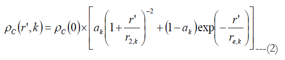
We generated a computational based map of ganglion cell distribution using eq. (1) and the assumption that within any one quadrant of the retina the iso-spacing contours are elliptical based forms. This idea leads to an equation to obtain the ganglion cell density at an arbitrary point {x, y } on the retina [37]:
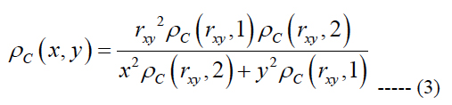
rxy is the radial eccentricity of the point {x, y} obtained as (x2 + y2)0.5, the indicators 1 and 2 in eq. (3) represent the vertical and horizontal meridians, respectively.
Figure 3(a), on top, shows the map of density distribution of RGCs from 1 to 16 mm of eccentricity. Peak ganglion cell density is found about 1 mm from the foveal center. At greater eccentricities within the central retina, ganglion cell density falls off with eccentricity more rapidly along the vertical meridian than along the horizontal meridian [25].
Photomicrographs of the retina of healthy human [39, 40], monkey [41] and mice [42] were considered in the estimation of the RGC distribution along the vertical section.
The ganglionic layer was divided in horizontal segments of equal thickness and cell nuclei were counted for each segment. Then, the results were averaged, normalized and plotted in red with circular markers against the thickness of the ganglionic layer, see Figure 3(b). The normalized results of each reference are shown in black using four different line styles.
The curve shape of the averaged and normalized data was fitted to a 3rd order polynomial and plotted in red with a solid line, see Figure 3(b). The curve peak amplitude (not included in Figure 3(b)) was build such that the integral of the polynomial over the RGC thickness yields the same realistic amount of cells per mm2 measured by Curcio et al., [25]. Thus, the polynomial:
Az3 + Bz2 + Cz + D ---- (4)
describes the volumetric cell density with numerical values of D = 0, C = 3.7392 ρC/t2, B = 0.741 ρC/t3, A = -4.4802 ρC/t4, where t is the RGC thickness. As a reminder ρC is the area cell density. Here we assumed that the cell distribution along the vertical section behaves the same for all four meridians.
In this present work, the distribution of RGC diameter found by Ryskamp et al., [43] was used in the reconstruction of the ganglion layer.
Raza et al., [44] measured the ganglion layer thicknesses for 43 eyes of 36 human healthy controls. In this study, the data found by Raza was used in the reconstruction of the ganglion layer. Since the ganglion layer becomes very thin in the periphery [44], there is no data available for the layer thickness away from the fovea. Thus, the layer thickness in the periphery was assumed to be equal to the maximum diameter of cells found by Ryskamp. The interpolated values of the thickness until the periphery were determined by shape preserving piecewise cubic interpolation of the thickness.
Consider an arbitrary electrode density and cell distribution. The condition to activate a single cell per stimulating electrode can be written as:
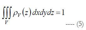
ρv is volumetric cell density described by the polynomial. V is the volume of stimulation obtained in Comsol Multiphysics and Matlab software, see section Materials and Methods - Volume Region of Stimulation.
Let us assume that the shape of the volume of stimulation forms one half of a spheroid with two equal semi-diameters described as d/2. Using the relationship of d2 = 1/ρE and rearranging eq. (5) we get:
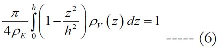
where the peak height for an electrode diameter of 5 μm is fitted to h = α•ρEβ in millimeters with values of 0.087 for α and -0.2 for β. The peak height of the volume region depends on the electrode diameter and density. The implicit solution of eq. (6) yields:
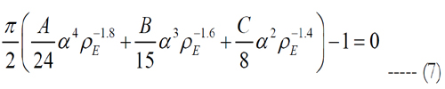
where Matlab is used to solve the roots of eq. (7). Since Matlab returned more than one solution, electrode pitches and peak heights of the volume of stimulation were determined using each electrode density, except of such with an imaginary part. Then, the volumes tested their stimulation of cells. The electrode density with cell activation closest to one is selected.
The spatial information of the biomimetic electrode array is obtained as follows. Consider a square region on the retina that is divided into small 32 by 32 regular square shapes with equal sizes labeled dr, where dr is the retinal pitch; Figure 3(a) on top. The retinal pitch area is defined as dr2.
The area cell densities ρc and ganglion layer thicknesses t inside each retinal pitch area were averaged and used in eq. 7 to obtain a local electrode density. This local electrode density is used to obtain the local electrode pitch, d, using eq. (1). The electrodes in the biomimetic electrode array are separated with a distance of d/2i-1 + d/2i. That is, the separation distance is equal to the sum of one half of the electrode pitch of the previous electrode d/2i-1 and one half of the electrode pitch of the actual electrode I/2i.
Figure 3(a), on top, shows only the area density distribution of RGCs. Within, a square region area is divided into small 32 by 32 regular squares with equal retinal pitches. As an exemplary case, we took a single retinal pitch area whence a local electrode density and electrode pitch are generated. The origin of the square region is fixed for all retinal pitches.
A Matlab script organized the data of the area density distribution of RGCs, thickness of the ganglion layer, cell spreading in the vertical section, assignment of the RGC diameter and the design of the biomimetic array to investigate the stimulation of RGCs per stimulating electrode.
The distribution of RGCs along the ganglion layer is as follows. Eq. 3 and the data from Raza A et al., (2015) [44] were used to obtain the area cell density and the ganglionic layer thickness as a function of the eccentricity, respectively. The area cell density and layer thickness were interpolated in two-dimensions such that each segment represented a small area on the retina. The function of the volumetric cell density, ρv(z), defined on [0, t] where t is the ganglion layer thickness was divided into segments of equal thickness. Riemann sum integration method was used to approximate the integral of each segment with an interval of 1/100 of the thickness of each segment. The results of the integration were multiplied by the corresponding small area on the retina to obtain the RGCs that were randomly located within each segment.
RGC diameters were randomly assigned per ganglion cell. The histogram that describes the distribution of the RGC size was strictly followed to generate a realistic representation of the cell dimensions along the retina.
The diameter of RGCs was randomly assigned as a function of retinal eccentricity as evidence shows that no relationship was observed between soma size and eccentricity for any cell group or subgroup [45].
RGC overlapping was addressed by removing the cell that intersects with an adjacent. This process was carried out only in the space relevant for electrode stimulation. That is, RGCs located within the vicinity until the peak heights were processed. RGCs outside this range were neglected for computational time purposes. Electrode stimulation of a single or nearby RGCs positioned randomly in the ganglionic layer must satisfy the following relationship:
r'' ≤ r ---- (8)
r’’ corresponds to the Euclidean distance from the center of the volume region of stimulation to the center of a RGC.
rV is computed as:
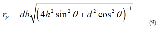
rV corresponds to the actual radius of the volume region of stimulation used for comparison. d relates the electrode pitch and h is the peak height of the volume of stimulation.
θ is calculated as:
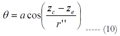
zc and ze relate to the center location of the RGC and the volume of stimulation in the z axis, respectively. Figure 3(c) shows an exemplary case for electrode stimulation.
The condition to compute the quantity of RGCs stimulated per electrode is as follows. If stimulation of an electrode is achieved inside its own volume, a counter increases its value by 1 in this specific electrode. Otherwise the counter remains unchanged.
The Matlab script was iterated 100 times in order to create a new random location of RGCs. This was carried out for a real case randomness scenario of RGCs, to obtain probabilistic values of the results and have meaningful conclusions about cell activation and electrode usage.
The biomimetic array was built by selecting a retinal pitch and forming a square region area where inside small 32 by 32 regular squares with equal sizes examine the surface of the retina; see figure 3(a), on top. The retinal pitches selected are 0.0025, 0.032, 0.09, 0.12, 0.135 and 0.425 mm. In figure 3(a), on bottom, six square regions are drawn to their corresponding retinal pitches. Each square region produces abiomimetic electrode array labeled AD1 until AD6, see figures 3(d) to 3(i). rp in this figure means retinal pitch.
The extent of the square regions is between 4° (1 mm) where peak cell density is located [25] and 62.3° (16 mm) of eccentricities. This boundary includes 1) the region until 10° (2.7 mm) needed for critical functions such as object recognition, reading and driving [46], 2) the region until 15° (4.06 mm) for the situations related to safe navigation in out-door environments [47, 48], and 3) 62.3° (16 mm) for possible movements of the electrode array inside the eye.
The retinal pitch started with a low value such that the electrode spreading can be similar to a square-grid distribution, figure 3(d). The last retinal pitch was selected such that the possible area on the retina at the superior meridian is covered, figure 3(i). This results to a total examined area on the retinal between 0.006 and 185 mm2. The origin of the square region is fixed for all retinal pitches. See figure 3(a), on bottom, for the extent of the square regions away from the origin.
In this report, single electrode stimulation is implemented with electrode diameter of 5 μm. The proximity of cells to the electrodes is 10 μm, see figure 2(b). The present work focuses on meridian maps of area cell density along the horizontal meridians (nasal and temporal) at the superior direction. This is mainly because 1) the highest ganglion cell densities are found in the horizontal meridian and 2) in peripheral retina densities in superior retina exceed those at the corresponding eccentricities in inferior retina by 60% [25].
RGC stimulation was investigated by relocating the biomimetic array due to the natural movements of the eye. This includes eccentricities from 4° (1 mm) until 37.2° (10 mm).
Charge-imbalanced rectangular pulse shape was applied with anodic first phase of 100μs pulse duration followed by the cathodic phase of 50μs pulse duration. Between the anodic and cathodic phases, the system is open-circuited with a delay of 100 μs.
The stimulating electrode array consisted of an active electrode is surrounded by eight grounds as seen in figure 3(c). The control of selecting the role of electrodes to function as active or ground is considered as seen in previous publications [27,28]. Active electrodes can have their own timeslot for stimulation [28]. In total, a 32 by 32 electrode array was implemented.
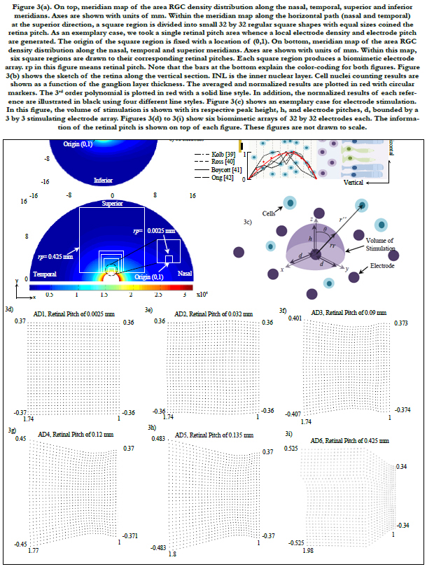
Figure 3(a). On top, meridian map of the area RGC density distribution along the nasal, temporal, superior and inferior meridians. Axes are shown with units of mm. Within the meridian map along the horizontal path (nasal and temporal) at the superior direction, a square region is divided into small 32 by 32 regular square shapes with equal sizes coined the retina pitch. As an exemplary case, we took a single retinal pitch area whence a local electrode density and electrode pitch are generated. The origin of the square region is fixed with a location of (0,1). On bottom, meridian map of the area RGC density distribution along the nasal, temporal and superior meridians. Axes are shown with units of mm. Within this map, six square regions are drawn to their corresponding retinal pitches. Each square region produces a biomimetic electrode array. rp in this figure means retinal pitch. Note that the bars at the bottom explain the color-coding for both figures. Figure 3(b) shows the sketch of the retina along the vertical section. INL is the inner nuclear layer. Cell nuclei counting results are shown as a function of the ganglion layer thickness. The averaged and normalized results are plotted in red with circular markers. The 3rd order polynomial is plotted in red with a solid line style. In addition, the normalized results of each reference are illustrated in black using four different line styles. Figure 3(c) shows an exemplary case for electrode stimulation. In this figure, the volume of stimulation is shown with its respective peak height, h, and electrode pitches, d, bounded by a 3 by 3 stimulating electrode array. Figures 3(d) to 3(i) show six biomimetic arrays of 32 by 32 electrodes each. The information of the retinal pitch is shown on top of each figure. These figures are not drawn to scale.
Results
Figure 3(a), on top, shows only the map the area density distribution of RGCs along the nasal, temporal, superior and inferior meridians. The axes are shown with units of millimeters. Within the meridian map along the horizontal meridians (nasal and temporal) at the superior direction, a square region is divided into small 32 by 32 regular square shapes with equal sizes labeled the retina pitch. As an exemplary case, we took a single retinal pitch area whence a local electrode density and electrode pitch are generated.
Figure 3(a), on bottom, shows the meridian map of the area density distribution of RGCs only along the nasal, temporal and superior meridians. Axes are shown with units of mm. Within this map, six square regions are drawn to their corresponding retinal pitches. Inside each, small 32 by 32 regular square shapes must be accommodated to obtain the spatial information of the biomimetic electrode array. Note that the bars at the bottom explain the color-coding for both figures. rp in this figure means retinal pitch.
Figure 3(b) depicts a sketch of the retina along the vertical section. Cell nuclei counting results are shown as a function of the ganglion layer thickness. The averaged and normalized results are plotted in red with circular markers. In addition, the normalized results of each reference are illustrated in black using four different line styles.
Figure 3(c) shows an exemplary case for electrode stimulation. In this figure, the volume of stimulation is shown with its respective peak height, h, and electrode pitches, d, bounded by a 3 by 3 stimulating electrode array.
Figures 3(d) to 3(i) illustrate six biomimetic arrays of 32 by 32 electrodes each. The distribution per electrode is governed by the retinal information inside each retinal pitch area where local area densities and ganglion layer thicknesses are averaged and used in eq. 7 to obtain a local electrode density. The electrode pitch can be computed with eq. (1) by a known electrode density. This electrode array allocates each electrode differently than the evenly distributed electrode array. Mainly, the former arrangement locates the electrodes according to their own electrode pitch.
Figures 4(a) to 4(c) show the averages and standard deviations of percentage of electrodes of RGC activation. Each bar graph represents the average of percentage of electrodes on a 32 by 32 biomimetic array that activated single RGCs (figure 4a), zero RGCs (figure 4b) and multiple RGCs (figure 4c). The x-axis relates to the location of the biomimetic array on the retina with coordinates (x, y), compare to figure 4(d). The axes in figure 4(d) are related to eccentricities in units of mm.
A total of 20 points were selected and distributed in the horizontal meridians (nasal and temporal) at the superior path. For organizing the data, all points were grouped in retinal regions according to their distance from the central point of the retina. These regions are located inside figure 4(d) labeled 1st, 2nd, 3rd and 4th and are related to figures 4(a) to 4(c).
Figure 4(e) plots the area of the array and the field of view as a function of the retinal pitch. Figure 4(f) exhibits the dependence of electrode distribution on the area cell density and the ganglion layer thickness (not shown). All results in our simulations were within the electrochemical safety region.
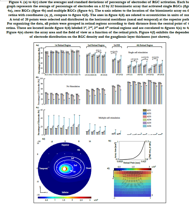
Figure 4. (a) to 4(c) show the averages and standard deviations of percentage of electrodes of RGC activation. Each bar graph represents the average of percentage of electrodes on a 32 by 32 biomimetic array that activated single RGCs (figure 4a), zero RGCs (figue 4b) and multiple RGCs (figure 4c). The x-axis relates to the location of the biomimetic array on the retina with coordinates (x, y ), compare to figure 4(d). The axes in figure 4(d) are related to eccentricities in units of mm. A total of 20 points were selected and distributed in the horizontal meridians (nasal and temporal) at the superior path. For organizing the data, all points were grouped in retinal regions according to their distance from the central point of the retina. These are located inside figure 4(d) labeled 1st, 2nd, 3rd and 4th retinal regions and are correlated to figures 4(a) to 4(c). Figure 4(e) shows the array area and the field of view as a function of the retinal pitch. Figure 4(f) exhibits the dependence of electrode distribution on the RGC density and the ganglionic layer thickness (not shown).
Discussion
In this report, the biomimetic electrode array examined RGC stimulation by changing the retinal pitch and the location of the array on the retina. In brief, the responses of single cell stimulation leveled off until the 3rd retinal region having a large retinal pitch and large array area. That is, single cell stimulation can be stable up to 30° of eccentricity in average and can produce a wide-ranging field of view. These findings are explained next.
This mathematical formulation presented in this report generates single cell activation at locations with high area density of RGCs, see eqs. 4 to 7. This is required to produce a high-resolution vision in retinal stimulation [46].
The inputs include the spatial distribution of RGCs in a perspective three-dimensional view and the thickness of the ganglion layer [44]. This spatial distribution includes the realistic area density [25] and the vertical distribution [39-42] of RGCs. The response of this formulation can be accurate for any threedimensional topography of RGCs and the depth of the ganglionic layer, outputting the electrode density that allows electrodes to stimulate single cells.
The retinal pitch, as it is decreased, the distribution of the biomimetic electrode array exhibits a shape that resembles a square-grid distribution, see figure 3(d). This arises because the average cell densities and ganglionic thicknesses of adjacent retinal pitch areas are similar to each other. Therefore, local electrode densities and electrode pitches are nearly unchanged.
The retinal pitch, as it is increased, the distribution of the biomimetic array varies according to a broader region of the retina. Area density of RGCs has its peak of around 1 mm away from the fovea. At greater eccentricities within the central retina, the area density of RGCs falls off with eccentricity more rapidly along the vertical meridian than the horizontal meridian [25], see figure 3(a), on top. The ganglion thickness declines rapidly along the vertical and horizontal meridians [44]. These rapid decays of area density of RGCs and ganglion layer thickness could indicate the incapability of electrodes to adapt their stimulation to the corresponding site at the retina.
In this regard, biomimetic electrode array can locate the electrodes with adjusted electrode densities to stimulate single cells. That is, a local electrode density with narrow electrode pitch will result from a high area density of RGCs and a small ganglion layer thickness. A broader electrode pitch will result from a small area density and a large ganglion layer thickness.
The 1st retinal region shown in figure 4(d) can be categorized as a critical region because its location lies between 4° (1 mm) where peak cell density is located [25] and 15° (4.06 mm) where critical functions such as object recognition, reading and driving [46] and situations related to safe navigation in dynamic out-door environments [47, 48] are processed.
As previously explained, the retinal pitch started with a low value such that the electrode spreading can be similar to a squaregrid distribution, see figure 3(d). As the retinal pitch increases, electrode distribution changes according to a different electrode pitch. This leads a gradual falloff of single stimulation of RGCs reaching a steady 40% of electrodes in average; see AD6 in figure 4(a).
However, as electrodes examine a broader region on the retina, the cases of no stimulation per electrode decrease, reaching a steady 20% of electrodes in average, see AD6 in figure 4(b). Misusing electrodes in retinal stimulation could lead to the generation of dark gaps at sites related in visual space with the location of the misused electrodes on the retina. Thus, electrodes require the activation of single or nearby RGCs to a feasible extent.
The percentage of electrodes stimulating a bundle of RGCs increases reaching 45% of electrodes in average.
In spite that the activation of packages of RGCs can restrict detailed perception and can generate neuron activity dissimilar from the healthy retina [49]; our simulation framework indicates that double and triple RGC activation per electrode dominate with an average percentage of 60% and 30%, respectively, of the total percentage of multiple stimulation per case. The rest of 10% can be assigned to quadruple activation per electrode.
Weiland and Humayun [36] reported that the stimulation per electrode site would ideally reach nearby cell bodies. This will ensure that the perception generated by stimulation will be small (on the order of the electrode) and related in visual space with the location of the electrode on the retina. Fried et al., [32] supported the use of small electrodes to activate small groups of cells. This would lead to high resolution patterns of prosthetic-elicited activity in neurons.
Although that the specific amount of nearby RGCs has not been reported yet, single localized stimulation ideally remains a target because RGCs are tightly-packed in the ganglionic layer, mainly at the fovea. Unique characteristics of the visual space are sent to the brain via temporal patterns of activity in RGC types. RGCs that are close to each other frequently transmit very different signals [13].
Epiretinal implants are located on the surface of the retina, near to the ganglion layer boundary. This location guarantees that the array is in close proximity to the RGCs. This is advantageous as lower thresholds of activation are required when the stimulating electrode is near to the target neurons [50]. However, natural movements of the eye could relocate the epiretinal design toward the large space in the vitreous cavity. Frequently, the eyes make rapid shifts in position about 2-3 times per second [51]. This would affect the stimulation of RGCs, particularly of single cells. Typically, a single retinal tack is used to fasten the implant to the retina [52].
That being said, the response of the biomimetic array should be reported in several locations on the retina. This response is shown in figures 4(a), 4(b) and 4(c) for the retinal regions 2nd, 3rd and 4th. The retinal pitch, as it is decreased, single stimulation of RGCs has a low percentage of electrodes in the periphery. This behavior can be attributed to the region of the retina being examined by the biomimetic array. In this case, the electrode array would have information of a small portion of the entire retinal surface; compare square regions in figure 3(a), on bottom. Hence, electrodes placed in this small region of the retina previously examined by the biomimetic array are preferable to activate single RGCs, whereas in the periphery groups of electrodes are misused, see AD1 to AD5 in figure 4(a).
The explanation of why groups of electrodes cannot activate a cell and are misused is as follows. RGCs have low density and large spacing between adjacent cells in the periphery. The cases of RGCs that are near one another are infrequently met. Thus, groups of electrodes with small electrode pitches (this is because of the small region with high density of cells formerly examined by the array) will have small volumes unfilled of cells and electrodes will be misused [53].
The retinal pitch, as it is increased, the region being securitized by the biomimetic array increases. This leads the electrode array to have larger information of the retina and abroader region where single cells can be activated, see AD6 in figure 4(a). In this particular electrode array, the stimulation of a single cell is leveled off until the 3rd region with a percentage of electrodes of 38% in average.
However, as the electrode array is shifted enough such that it is within the 4th retinal region, the percentage of electrodes that cannot stimulate dominates, reaching 80% in average for all biomimetic arrays. This suggests that the biomimetic array must be fastened close to the fovea for practical applications. This results the stimulation of the biomimetic electrode array within the critical region of ± 15° of eccentricity where activities demanding visual detail are processed [46-48].
Another consequence of the biomimetic array being relocated away from the fovea is a reduction of multiple RGC activation per electrode. This can be explained as follows. RGCs in the periphery have low density and large spacing between neighboring cells. The situations of RGCs close to each other are sporadically met. In addition, RGCs located in the ganglion layer have their peak nearly in the center; see figure 3(b). Thus, as the area cell density is reduced, single electrode sites are more concentrated to stimulate single cells. However, groups of electrodes are carelessly used [53].
The relocating points of the biomimetic array were grouped in retinal regions according to their distance from the central point of the retina, see in figure 4(d). These are located inside the 1st, 2nd, 3rd and 4th retinal regions.
In figures 4(a) to 4(c), the average percentage of electrodes that activate a single RGC (figure 4a), zero RGC (figure 4b) and multiple RGCs (figure 4c) remained roughly steady per retinal region and biomimetic array. This suggests that the stimulation of cells at an arbitrary location on the retina would have a similar response to a corresponding retinal region and biomimetic array.
The electrodes in the biomimetic array are separated with a distance of d/2i-1 + d/2i. That is, the separation distance is equal to the sum of one half of the electrode pitch of the previous electrode d/2i-1 and one half of the electrode pitch of the actual electrode d/2i. This array locates electrodes differently than the previously described evenly distributed array, see figure 1(b). Mainly, the former array locates the electrodes according to their own electrode pitch, whereas the latter assigns a single electrode pitch for the complete array.
For the former case, this could result to an uneven spread of the current to the surrounding grounds. That is, if the active electrode has an electrode pitch much different to the surrounding grounds, the stimulus could generate variations in the volume of stimulation.
In Villarreal DL, et al., (2017) [14], the volume region of stimulation was simplified as one half of a spheroid with two equal semi-diameters described as d/2 and a peak height that depends on the electrode diameter and density. This arrangement follows a 3 by 3 stimulating electrode array, square-grid distribution and the active electrode surrounded by eight grounds. Comsol simulations generated a volume of stimulation that intersected with the ganglion layer boundary and produced a circular shape that followed a ‘sinking at the diagonals’ shape with an average distance of 80% of d/2, see figure 5(a). This circular shape was coined the activation area.
We addressed this issue by finding in Comsol how much the volume of stimulation deviates from being one half of a spheroid for the cases of the retinal pitches until 0.425 mm. We used the simplification in Villarreal DL, et al., (2017) [14] as a basis of comparison. That is, an activation area with a distance more than 80% of d/2 of the most sunken diagonal is accepted. The method of building the volume of stimulation is explained in section Materials and Methods - Volume Region of Stimulation. For more information about the activation area and the volume of stimulation, see Villarreal DL, et al., (2017) [14].
A 3 by 3 stimulating electrode array that consists of an active electrode surrounding by eight grounds was considered. Each electrode was separated with its corresponding electrode pitch. This was carried out for the entire biomimetic array of 32 by 32 electrodes.
The retinal pitch, as it is increased, we mainly found two patterns of electrode distributions different from a square-grid distribution. These are presented in figures 5(b) and 5(c). The biomimetic electrode arrayin figure 5(d) corresponds to a retinal pitch of 0.425 mm.
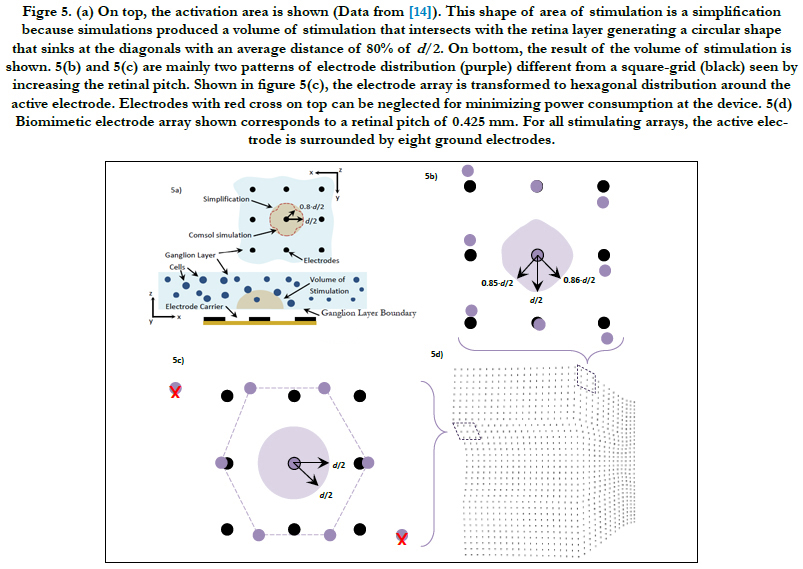
Figre 5. (a) On top, the activation area is shown (Data from [14]). This shape of area of stimulation is a simplification because simulations produced a volume of stimulation that intersects with the retina layer generating a circular shape that sinks at the diagonals with an average distance of 80% of d/2. On bottom, the result of the volume of stimulation is shown. 5(b) and 5(c) are mainly two patterns of electrode distribution (purple) different from a square-grid (black) seen by increasing the retinal pitch. Shown in figure 5(c), the electrode array is transformed to hexagonal distribution around the active electrode. Electrodes with red cross on top can be neglected for minimizing power consumption at the device. 5(d) Biomimetic electrode array shown corresponds to a retinal pitch of 0.425 mm. For all stimulating arrays, the active electrode is surrounded by eight ground electrodes.
In figure 5(b), the maximum deviation of the activation area reached 85% and 86% of d/2 at their respective diagonal. The peak height was not disturbed. Concerning figure 5(c), we observed that neither the activation area nor the peak height was disturbed. This kind of distribution was seen only in retinal pitches larger than 1/3 mm. While electrodes follow their own electrode pitches, the first and last rows are shifted in opposite directions forming a hexagonal electrode distribution. This kind of distribution was investigated in earlier works. Wong et al., [54] compared cortical stimulation of one-and six-ground settings of current steering techniques. Experimental findings in animals suggested that six-ground setting was efficient because of the smaller area of cortical activation and the reduction of unwanted interactions between multiple stimulation sites. These results suggest that the volume of stimulation within the biomimetic electrode array can be simplified as a spheroid with two equal semi-diameters described as d/2 and a peak height h. However, the cases of the retinal pitch that deviate the volume of stimulation enough such that its shape is other than one half of a spheroid should be considered separately. In this report, the biomimetic array considered retinal pitches until 0.425 mm to cover the possible area at superior meridian. See figure 3(a) on bottom for the extent of the square regions away from the origin.
Here, the advantages to develop a biomimetic electrode array are listed. In this case, the biomimetic array with retinal pitch of 0.425 mm is compared with lower retinal pitch arrays.
As the retinal pitch increases, single localized stimulation leveled off until the 1st region of the retina with high area cell density, see figure 4(a) for AD1 to AD5. As the retinal pitch reaches 0.425 mm, single cell stimulation stabilized within the 3rd retinal region, see fig. 4(a) for AD6. This stimulating behavior indicates that single localized stimulation can reach steady-state within ± 10° of eccentricity away from the fovea and further. This also suggests that single localized stimulation can be ensured for a wide region on the retina. Table 3 lists the extent of the retinal regions away from the fovea.
The region within ± 10° of eccentricity is categorized as a space with large quantity of RGCs and thus needed for critical functions, such as object recognition, reading and driving [46]. Single cell stimulation is required within this region to address activities that demandhigh visual detail.
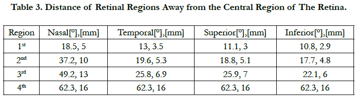
Table 3. Distance of Retinal Regions Away from the Central Region of The Retina.
Despite that reaching single cells per electrode can enhance visual perception [13], electrodes need to be positioned close to each other in the array. This would lead to a more precise stimulating region. However, this causes that the visual field of view generated by stimulation may be small because it is directly related to the size of the stimulated area at the retina and hence to the size of the electrode array. Tychsen [55] estimated that the projected visual field of view for every 1 mm of the retina is about 3.35°.
An increase of the retinal pitch leads the biomimetic array to investigate a broader area on the retina. Some of that area could have an area density distribution of RGCs and a ganglion layer thickness that both generate electrodes with low electrode densities and large electrode pitches. Hence, a rise change in the retinal pitch causes the area of the array to increase.
In figure 4(a), 0.425 mm retinal pitch biomimetic array generates a steady response of single cell stimulation within ± 30° of eccentricity in average. This direct dependence of the area of the arrayon the retinal pitch leads to a wider field of view while single cell stimulation remains stable. This is a major advantage of the biomimetic electrode array. Figure 4(e) shows the relationship between both the area of the array and field of view (y-axis) and retinal pitch (x-axis).
An increase of the retinal pitch more than 1/3 mm causes the electrodes to procedure a hexagonal pattern distribution, see figure 4(c). This has mainly three advantages.
First, experimental evidence suggested that six-ground setting is efficient because a smaller area of stimulation was generated and unwanted interactions among multiple stimulation sites were reduced [54]. Second, the distribution of current density can be restricted in a small region that surrounds the ganglion cell. This results in a more controlled stimulation area [54]. Third, the total power consumption that would result from the power of the transistors that drive the electrodes and the power per stimulating channel will be reduced. This means a reduction of the power dissipated as heat by the device.
The disadvantages to develop a biomimetic electrode array are listed. Here, the biomimetic array with retinal pitch of 0.425 mm is compared with lower retinal pitch arrays.
A rise change of the retinal pitch causes the activation of multiple RGCs, see figure 4(c). The reason for such behavior is as follows. The retinal pitch, as it is increased, causes the electrode array to inspect a wider region on the retina. This generates a unique electrode distribution where electrode pitches become larger along the array, compare figures. 3(d) to 3(i). As the array is located inside the 1st retinal region, single RGCs, having the highest area density and smallest spacing between them, will be activated by electrodes with small electrode pitch. However, multiple cells could be activated in cases with larger electrode pitches.
In spite that the activation of nearby cells can restrict detailed perception and produce RGC activity different from the healthy retina [49], our simulation framework indicates that double and triple RGC activation per electrode dominate with an average percentage of 60% and 30%, respectively, of the total percentage of multiple cell stimulation per case. The rest can be assigned to quadruple RGC activation per electrode.
Larger retinal pitches generate a characteristic electrode array as electrodes follow different spatial information that associate the location of each electrode. This would cause an increased hardware effort and human-hour work to produce such electrode array.
Before hand that any stimulation is given, patients report a grayish background covering their visual fields [49]. In response to direct activation of ganglion cells with electric stimulus, patients frequently report a bright percept that is surrounded by a dark background [2, 16, 56].
While electrodes stimulate nearby RGCs, the phosphene frequently reported by the patients can be related to the response of a cluster of ON type cells [14]. This is because 1) a bright percept surrounded by a dark background is the frequent response while RGCs are electrically stimulated [2, 16, 56]; 2) a bright phosphene results from preferential activation of ON versus OFF type ganglion cells [51]; 3) the bright response of ON type cells over shadows the response of OFF cells when both are activated identically by electric stimulation [51]; 4) activation thresholds for electrical stimulation of the five numerically dominant retinal ganglion cell types (ON and OFF midget, ON and OFF parasol, and small bistratified) are similar [26, 57, 58]; 5) ON and OFF type cells are spatially intermixed [59].
While stimulus is delivered to the cells, the volume region of stimulation can indicate the stimulation of RGCs regardless of the type and class because cells are mixed in space [59] and have similar activation thresholds [26, 57, 58]. ON and OFF type cells are contained within the volume of stimulation. Hence, this region can estimate the amount stimulated RGCs with a given set of stimulation parameters [14].
Despite that the volume region of stimulation can indicate the stimulation of RGCs regardless of the type and class, this region can approximate the size and shape of the elicited phosphene because it implicitly shows a volume that can be related to the bright response of ON type cells. This indirect approach to map the elicited phosphene relates to the respond of actual ON type cells being electrically stimulated [14].
Both ON and OFF type cells can be stimulated with arrays of electrodes with small diameter at comparable threshold levels [57]. Margalit [60] reported similar findings in tiger salamander retina. In many cases, a single cell could be individually stimulated without activating adjacent cells of the same type or other types [26].
Operating with large retinal pitch will allow the biomimetic array to stabilize the stimulation of single cells from locations with high cell density to 30° of eccentricity in average, figure 4(a). Likewise, misused electrode situations are reduced; figure 4(b). Thus, the generations of dark gaps at locations related in visual space with the location of the misused electrodes on the retina are reduced. Electrodes require the capacity to activate single or nearby RGCs to a feasible extent. The rest would activate double and triple RGCs per stimulating electrode, figure 4(c). Lastly, operating with large retinal pitch will allow a broad array area that produces a wide field of view.
Placing the biomimetic array near the fovea will allow the activation of RGCs in the region of high cell density. This is a requisite in visual prostheses because actions that require high visual detail are processed within ±15° of eccentricity.
Securing the biomimetic array near the fovea will avoid the relocation of the array and thus a decrease of the situations of single cell stimulation. This relocation mainly occurs after natural movements of the eye [61]. This could shift the array to the large space in the vitreous cavity and change the direction of stimulation. Frequently, a single retinal tack is used to fasten the implant to the retina [52].
Applying short-current pulses of 100μs or less are preferable because passing retinal ganglion cell axons can be avoided while stimulation. Choosing that pulse duration, the amount of current needed to generate the response of a cell is much lower than that required to generate an axonal response [62]. Greenberg et al., [63] supported these observations by reporting that axonal threshold was 20% higher than that of the retinal ganglion cell. Experimental findings by Jepson [13] exhibited single spike responses with submillisecond latency which is a characteristic of direct ganglion cell activation. In this study, short pulse durations of 100 μs and small electrodes of 15 μm of diameter were used. Short-current pulses have an additional advantage of reducing the charge required for excitation. With reduced charge, the probability of electrode corrosion and tissue damage is lessened [62].
In this study, charge-imbalanced rectangular pulse shape was applied across 5 μm electrode diameter with anodic first phase of 100μs pulse duration followed by the cathodic phase of 50μs pulse duration.
Conclusion
This present work examined the stimulation of RGCs using the biomimetic electrode array at locations in the retina with high area cell density. This is a requisite in visual prostheses because activities demanding visual detail are processed in these regions. We also examined RGC stimulation at locations in the retina with low area density as the biomimetic array could be relocated due to the natural movements of the eye.
Our simulation framework included an accurate three-dimensional reconstruction of the retina and ganglionic layer for an epiretinal design.
Single cell stimulation was realized along the retinal regions near the fovea, which is required in humans for activities where visual detail is of primary importance and thus relevant for high resolution vision. Single localized responses leveled off until 30° of eccentricity in average using the biomimetic electrode array with large array area. That is, the biomimetic array can produce a stable stimulation of single cells and a broad field of view for a wide region of the retina.
The applicability of the biomimetic electrode array not only can improve single cell activation, but also can yield valuable strategies to increase the area of the array and produce a wide-ranging field of view.
References
- Humayun MS, de Juan E Jr, Dagnelie G, Greenberg RJ, Probst RH, Phillips DH, et al. Visual perception elicited by electrical stimulation of retina in blind humans. Arch Ophthalmol. 1996 Jan;114(1):40– 46. PubMed PMID: 8540849.
- Humayun MS, de Juan E Jr, Weiland JD, Dagnelie G, Katona S, Greenberg R, et al. Pattern electrical stimulation of the human retina. Vision Res. 1999 Jul;39(15):2569–2576. PubMed PMID: 10396625.
- Humayun MS, Weiland JD, Fujii GY, Greenberg R, Williamson R, Little J, et al. Visual perception in a blind subject with a chronic microelectrode retinal prosthesis. Vision Res. 2003 Nov;43(24):2573– 2581. PubMed PMID: 13129543.
- Humayun MS, Weiland JD, Fujii GY, Greenberg R, Williamson R, Little J, et al. Visual perception in a blind subject with a chronic microelectrode retinal prosthesis. Vision Res. 2003 Nov;43(24):2573– 2581. PubMed PMID: 13129543.
- Mahadevappa M, Weiland J, Yani D, Fine I, Greenberg R, Humayun M. Perceptual thresholds and electrical impedance in 3 retinal prosthesis subjects. IEEE Trans Neural Syst Rehabil Eng. 2005 Jun;13(2):201–206. PubMed PMID: 16003900.
- Rizzo JF, Wyatt JL. Prospects for a visual prosthesis. The Neuroscientist. 1997 Jul;3(4):251.
- Rizzo JF, Wyatt JL. Methods and Perceptual Thresholds for Short-Term Electrical Stimulation of Human Retina with Microelectrode Arrays. Invest Ophthalmol Vis Sci. 2003 Dec;44(12):5355-61. PubMed PMID: 14638738.
- Klauke S, Goertz M, Rein S, Hoehl D, Thomas U, Eckhorn R, et al. Stimulation with a Wireless Intraocular Epiretinal Implant Elicits Visual Percepts in Blind Humans. Invest Ophthalmol Vis Sci. 2011 Jan;52(1):449-455. doi:10.1167/iovs.09-4410. PubMed PMID: 20861492.
- Eger M, Eckhorn R, Wilms M, Schanze T, Hesse L, Walter P, et al. Visual resolution with retinal implants estimated from recordings in cat visual cortex. Vision Res. 2006 Sep;46(17):2675–2690. PubMed PMID: 16571357.
- Keserü M, Feucht M, Bornfeld N, Laube T, Walter P, Rössler G, et al. Acute electrical stimulation of the human retina with an epiretinal electrode array. Acta Ophthalmol. 2012 Feb;90(1):e1-8. PubMed PMID: 22067614.
- Humayun M, Dorn JD, da Cruz L, Dagnelie G, Sahel JA, Stanga PE, et al. Interim results from the international trial of second sight’s visual prosthesis. Ophthalmol. 2012 Apr;119(4):779–788. PubMed PMID: 22244176.
- Stingl K, Bartz-Schmidt KU, Besch D, Braun A, Bruckmann A, Gekeler F, et al. Artificial vision with wirelessly powered subretinal electronic implant alpha-IMS. Proc Biol Sci. 2013 Feb 20;280(1757):1–8. PubMed PMID: 23427175.
- Jepson LH, Hottowy P, Mathieson K, Gunning DE, Dąbrowski W, Litke AM, et al. Spatially Patterned Electrical Stimulation to Enhance Resolution of Retinal Prostheses. J Neurosci. 2014 April 2;34(14):4871– 4881. PubMed PMID: 24695706.
- Villarreal DL, Schroeder D, Krautschneider WH. A Treatise of the Physical Aspects of Phosphenes and Single-Cell Selectivity in Retinal Stimulation. Int J Comput Neural Eng. 2017 Sep 23;4(2):55-70.
- Brindley GS, Lewin WS. The sensations produced by electrical stimulation of the visual cortex. J Physiol. 1968 May;196(2):479–493. PubMed Central PMCID: PMC1351724.
- Rizzo JF, Wyatt J, Loewenstein J, Kelly S, Shire D. Perceptual efficacy of electrical stimulation of human retina with a microelectrode array during shortterm surgical trials. Invest Ophthalmol Visual Sci. 2003 Dec;44(12):5362–5369. PubMed PMID: 14638739.
- Veraart C, Raftopoulos C, Mortimer JT, Delbeke J, Pins D, Michaux G, et al. Visual sensations produced by optic nerve stimulation using an implanted self-sizing spiral cuff electrode. Brain Res. 1998 Nov;813(1):181–186. PubMed PMID: 9824694.
- Wilke R, Gabel VP, Sachs H, Bartz Schmidt KU, Gekeler F, Besch D, et al. Spatial Resolution and Perception of Patterns Mediated by a Subretinal 16-Electrode Array in Patients Blinded by Hereditary Retinal Dystrophies. Invest Ophthalmol Visual Sci. 2011 Jul 29;52(8): 5995-6003. doi:10.1167/iovs.10-6946. PubMed PMID:21693599.
- Yin S, Lovell NH, Suaning GJ, Dokos S. A Continuum Model of the Retinal Network and its Response to Electrical Stimulation. Conf Proc IEEE Eng Med Biol Soc. 2010;2010:2077-80. PubMed PMID: 21095947.
- Abramian M, Lovell NH, Morley JW, Suaning GJ, Dokos S. Computational Model of Electrical Stimulation of a Retinal Ganglion Cell with Hexagonally Arranged Electrodes. Conf Proc IEEE Eng Med Biol Soc. 2012;2012:3029-3032. PubMed PMID:23366563.
- Kasi S, Brugger J, Renaud PH, de Rooij N, Cosendai G, Giungliano M. Analysis of Factors Affecting the Performance of Retinal Prostheses Using Finite Element Modelling of Electric Field Distribution in the Retina. PhD Thesis, June 2011.
- Werginz P, Benav H, Zrenner E, Rattay F. Modeling the response of ON and OFF retinal bipolar cells during electric stimulation. Vision Res. 2015 Jun;111(Pt B):170-81. PubMed PMID:25499837.
- Kasi H, Hasenkamp W, Cosendai G, Bertsch A, Renaud P. Simulation of epiretinal prostheses - Evaluation of geometrical factors affecting stimulation thresholds. J NeuroEng Rehabil. 2011 Aug 19;8:44. PubMed PMID: 21854602.
- Rodger DC, Fong AJ, Li W, Ameri H, Ahuja Ak, Zhong H, et al. Flexible parylene-based multielectrode array technology for high- density neural stimulation and recording. Sensors and Actuators B: Chemical. 2008 Jun 16;132(2):449-460.
- Curcio C, Allen KA. Topography of Ganglion Cells in Human Retina. J Comp Neurol. 1990 Oct 1; 300(1):5-25. PubMed PMID: 2229487.
- Jepson L, Hottowy P, Mathieson K, Gunning DE, Dabrowski W, Litke AM, et al. Focal Electrical Stimulation of Major Ganglion Cell Types in the Primate Retina for the Design of Visual Prostheses. J Neurosci. 2013 Apr 24;33(17):7194–7205. PubMed PMID: 23616529.
- Luján VD, Schroeder D, Krautschneider WH. Feasibility Study of a 1000+ Electrode Array in Epiretinal Prosthesis. Intl J Pharma Med Biol Sci. 2016 July;5(3):163-170. 10.18178/ ijpmbs.5.3.163-170.
- Meza-Cuevas MA, Schroeder D, Krautschneider WH. A scalable 64 channel neurostimulator based on a hybrid architecture of current steering DAC. In Proceeding Middle East Conference on Biomedical Engineering, 2014 Feb 17-20; IEEE, Doha, Qatar; 2014.
- Fohlmeister J, PA Coleman, RF Miller. Modeling the repetitive firing of retinal ganglion cells. Brain Res. 1990 Mar 5;510(2):343-345. PubMed PMID: 2331606.
- Hodgkin A, Huxley AF. A quantitative description of membrane current and its application to conduction and excitation in nerve. J Physiol. 1952 Aug 2;117(4):500-544. PubMed PMID: 1392413.
- Joucla S, Glière A, Yvert B. Current approaches to model extracellular electrical neural micro stimulation. Front Comput Neurosci. 2014 Feb 19;8:13. PubMed PMID: 24600381.
- Fried S, Hsueh HA, Werblin FS. A Method for Generating Precise Temporal Patterns of Retinal Spiking Using Prosthetic Stimulation. J Neurophysiol. 2006 Feb;95(2):970–978. PubMed PMID: 16236780.
- Sohee K, Normann RA, Harrison R, Solzbacher F. Preliminary study of the thermal impact of a microelectrode array implanted in the brain. Conf Proc IEEE Eng Med Biol Soc. 2006;1:2986-9.PubMed PMID: 17946999.
- Singh V, Roy A, Castro R, McClure K, Dai R, Agrawal R, et al. On the thermal elevation of a 60-electrode epiretinal prosthesis for the blind. IEEE Trans Biomed Circuits Syst. 2008 Nov 18;2(4):289-300.
- Duay J, Gillette E, Liu R, Lee SB. Highly flexible pseudocapacitor based on freestanding heterogeneous MnO2/conductive polymer nanowire arrays. Phys Chem Chem Phys. 2012 Mar 14; 14(10):3329–3337. PubMed PMID: 22298230.
- Weiland JD, Humayun MS. Retinal Prosthesis. IEEE Trans Biomed Eng. 2014 Apr 2;61(5):1412-1424. PubMed Central PMCID: PMC4356127.
- Watson A. A formula for human retinal ganglion cell receptive field density as a function of visual field location. J Vis. 2014 Jun 30;14(7):15. PubMed PMID: 24982468.
- Curcio CA, Sloan KR, Kalina RE, Hendrickson AE. Human photoreceptor topography. J Comp Neurol. 1990 Feb 22;292(4):497-523. PubMed PMID: 2324310.
- Kolb H, Fernandez E, Nelson R. Webvision: The Organization of the Retina and Visual System. Salt Lake City (UT): University of Utah Health Sciences Center. 1995. PubMed PMID: 21413389.
- Ross MH, Kaye GI, Pawlina W. Histology, a Text and Atlas: with cell and molecular biology. 4th ed. Philadelphia: Lippincott Williams & Wilkins, 2003.
- Boycott B, Dowling J, Kolb H. Organization of the primate retina: light microscopy. Phil Trans. 1969 Mar 27; 225(799):109-184.
- Ong JM, Zorapapel NC, Rich KA, Wagstaff RE, Lambert RW, Rosenberg SE, et al. Effects of Cholesterol and Apolipoprotein E on Retinal Abnormalities in ApoE-Deficient Mice. Invest Ophthalmol Vis Sci. 2001 Jul;42(8):1891-1900. PubMed PMID: 11431458.
- Ryskamp DA, Witkovsky P, Barabas P, Huang W, Koehler C, Akimov NP, et al. The Polymodal Ion Channel Transient Receptor Potential Vanilloid 4 Modulates Calcium Flux, Spiking Rate, and Apoptosis of Mouse Retinal Ganglion Cells. J Neurosci. 2011 May 11;3(19):7089 –7101. PubMed PMID: 21562271.
- Raza A, Hood DC. Evaluation of the Structure–Function Relationship in Glaucoma Using a Novel Method for Estimating the Number of Retinal Ganglion Cells in the Human Retina. Invest Ophthalmol Vis Sci. 2015 Aug;56(9):5548-5556.
- Wenzhi Sun, Li N, He S. Large‐scale morphological survey of mouse retinal ganglion cells. J Comp Neurol. 451(2):115-126. PubMed PMID: 12209831.
- Nelson P, Aspinall P, Papasouliotis O, Worton B, O’Brien C. Quality of life in glaucoma and its relationship with visual function. J Glaucoma. 2003 Apr;12(12):139–150. PubMed PMID: 12671469.
- Cha K, Horch KW, Normann RA. Mobility performance with a pixelized vision system. Vision Res. 1992 Jul;32(7):1367–1372. PubMed PMID: 1455709.
- Geruschat DR, Turano KA, Stahl JW. Traditional measures of mobility performance and retinitis pigmentosa. Optom Vis Sci. 1998 Jul;75(7):525–537. PubMed PMID: 9703042.
- Horsager A, Fine I. The perceptual effects of chronic retinal stimulation. In: Dagnelie G, editor. Visual Prosthetics: Physiology, Bioengineering, Rehabilitation. Springer: US. 2011. 271-300. DOI: 10.1007/978-1-4419-0754- 7_14.
- de Balthasar C, Patel S, Roy A, Freda R, Greenwald S, Horsager A, Mahadevappa M, et al. Factors affecting perceptual thresholds in epiretinal prostheses. Invest Ophthalmol Vis Sci. 2008 Jun;49(6):2303–2314.
- Freeman D, Rizzo JF, Fried SI. Encoding visual information in retinal ganglion cells with prosthetic stimulation. J Neural Eng. 2011 Jun;8(3):035005. PubMed PMID: 21593546.
- Ahuja AK, Dorn JD, Caspi A, McMahon MJ, Dagnelie G, da Cruz L, et al. Blind subjects implanted with the Argus II retinal prosthesis are able to improve performance in a spatial-motor task. Br J Ophthalmol. 2011 Apr;95(4):539–543. PubMed PMID: 20881025.
- Lujan VD, Schroeder D, Krautschneider WH. Novel Method for Realizing 1000+ Electrode Array in Epi- or Subretinal Prosthesis. Intl J Pharma Med Biol Sci. 2016 Jul;5(3):146-153. 10.18178/ijpmbs.5.3.146-153.
- Wong YT, Dommel N, Preston P, Hallum LE, Lehmann TS, Lovell NH, et al. Retinal neurostimulator for multifocal vision prosthesis. IEEE Trans Neural Syst Rehabil Eng. 2007 Sep;15(3):425–434. PubMed PMID: 17894275.
- Tychsen L. In: Hart WM, editor. Binocular Vision, in Adler's physiology of the eye: clinical application . 9th ed. St. Louis: Mosby; 1992. 773-853.
- Zrenner E, Bartz-Schmidt KA, Benav H , Besch D , Gabel VP, Greppmaier U, et al. Subretinal electronic chips allow blind patients to read letters and combine them into words. Proc Biol Sci. 2011 May 22;278(1711):1489–97. PubMed Cental PMCID: PMC3081743.
- Sekirnjak C, Hottowy P, Sher A, Dabrowski W, Litke AM, Chichilnisky EJ. High-resolution electrical stimulation of primate retina for epiretinal implant design. J Neurosci. 2008 Apr 23;28(17):4446-56.
- Tsai D, Morley JW, Suaning GJ, Lovell NH. Direct activation and temporal response properties of rabbit retinal ganglion cells following subretinal stimulation. J Neurophysiol. 2009 Nov;102(5):2982–93. PubMed PMID: 19741103.
- Dacey DM. Origins of perception: retinal ganglion cell diversity and the creation of parallel visual pathways. In: Gazzaniga MS, editor. The cognitive neurosciences. Cambridge, MA: MIT; 2004. 281-301.
- Margalit E, Thoreson WB. Inner retinal mechanisms engaged by retinal electrical stimulation. Invest Ophthalmol Vis Sci. 2006 Jun;47(6):2606–2612. PubMed PMID: 16723477.
- O'Brien EE, Greferath U, Vessey KA, Jobling AI, Fletcher EL. Electronic restoration of vision in those with photoreceptor degenerations. Clin Exp Optom. 2012 Sep;95(5):473-483. PubMed PMID: 22823954.doi:10.1111/j.1444-0938.2012.00783.x
- Jensen RJ, Ziv OR, Rizzo JF. Thresholds for Activation of Rabbit Retinal Ganglion Cells with Relatively Large, Extracellular Microelectrodes. Invest Ophthalmol Vis Sci. 2005 Apr;46(4):1486–1496. PubMed PMID: 15790920.
- Greenberg RJ, Velte TJ, Humayun MS, Scarlatis GN, de Juan E. A computational model of electrical stimulation of the retinal ganglion cell. IEEE Trans Biomed Eng. 1999 May;46(5):505-514. PubMed PMID: 10230129.