Study the Performance of an Organic Rankine Cycle for Thermal Absorption and Recovery from the Scramjet Cooling Heat
Xinchun Li1*, Wang Z2, Niu Y2
1 The Air Force Xi’an Flight Academy, Xi’an, China.
2 Science and Technology on Scramjet Laboratory, National University of Defense Technology, Changsha, China.
*Corresponding Author
Xinchun Li,
The Air Force Xi’an Flight Academy, Xi’an710300, China.
Tel: 13152456060
Fax: +86 731 84512301
Email: xch_lee@163.com
Received: April 06, 2019; Accepted: April 09, 2019; Published: April 11, 2019
Citation:Xinchun Li, Wang Z, Niu Y. Study the Performance of an Organic Rankine Cycle for Thermal Absorption and Recovery from the Scramjet Cooling Heat. Int J Aeronautics Aerospace Res. 2019;6(3):192-199. doi: dx.doi.org/10.19070/2470-4415-1900023
Copyright: Xinchun Li© 2019. This is an open-access article distributed under the terms of the Creative Commons Attribution License, which permits unrestricted use, distribution and reproduction in any medium, provided the original author and source are credited.
Abstract
An Organic Rankine Cycle (ORC) for thermal absorption and recovery system is proposed for cooling scramjet. The heat which must be taken away by fuel coolant from cooling scramjet is converted to other forms of energy. The performance parameter of an ORC thermal management system has been performed and the thermodynamic analysis method of the system is depicted. The efficiency, the output power of the system and the multiplication ratio of fuel heat sink with different working fluids by evaporation pressure and condensation temperature are evaluated. Numerical results indicate that the performance parameters have different changing with evaporation pressure and condensation temperature. Therefore, it can be concluded from thermodynamic analysis that valuable output power can be drawn by employing an ORC thermal absorption and recovery system for hypersonic vehicles
2.Abbreviations
3.Introduction
4.An ORC Power Generation System Description
5.Parameters Analysis
6.Thermodynamic Analysis Method
7.Results and Discussion
8.Conclusion
9.References
Keywords
Energy Recovery; Scramjet; ORC; Output Power; Fuel Coolant.
Abbreviations
ORC: Organic Rankine Cycle; TEG: Thermoelectric Generator; NIST: National Institute of Standards and Technology.
Introduction
The issue of hypersonic airbreathing vehicle [1-3] has been studied for many years. With the high flight speed, the structure and thermal protection for hypersonic vehicle is great importance [4]. The scramjet has great amount of heat flux which is about 7~8MW/m2 in NASA-Langley airframe propulsion integrated ramjet engine [5]. Therefore, cooling scramjet is one of the critical technologies for airbreathing hypersonic vehicle equipped with scramjet. The regenerative cooling cycle is the most commonlyused techniquefor scramjet cooling [6]. During the cooling process, the fuel coolant flows through the cooling passage for cooling the structure [7, 8] and then flows to the combustion chamber for burning [9].
Regenerative cooling has been playing an important role on scramjets for safe sustained-operation [10]. However, fuel coolant can only cool the scramjet components such as combustion chamber, and the high temperature and heat flux of the scramjet wall have not been effectively utilized in a conventional thermal conversion way to produce electricity. There once existed a new Re-cooling Cycle which contained a turbine to transfer enthalpy from fuel to mechanical work and electric power [11, 12]. However, only part of fuel heat is converted to mechanical power [13, 14]. In general, the electrical efficiency of Re-cooling Cycle is relatively low.
Energy recovery has been a hot issue in all kinds of engines in recent years. In the case of waste heat recovery the ORC is a device for directly converting thermal energy into electrical energy [15]. As a possible alternative to the effective use of limited resources to reduce the fuel flow for cooling, an ORC power generation system for cooling scramjet based on the thermodynamic principle is performed. ORC has been used in many fields for energy recovery [16-18]. Önder [19] has proposed an organic Rankine for power generation from waste heat recovery in steel industry. The study includes energy and exergy analysis on an ORC. Liu [20] has analyzed the sensitivity of system parameters to the performance of the ORC system quantitatively. A thermodynamic model of the ORC system has been developed and verified for building binary-cycle geothermal power plants. Carcasci [21] has proposed an organic Rankine cycle combined with a gas turbine in order to convert the gas turbine waste heat into electrical power. Miller et al.,[22] tried to combine both TEG and ORC (Thermoelectric Generator and Organic Rankine Cycle) for power generation to recover heat from engines. However, the property of ORC power generation system for scramjet is relative scarce.
In this paper, an ORC for thermal absorption and recovery system is proposed firstly, and there is part of the heat from cooling scramjet and it would be converted to other forms of energy. The hydrocarbon fuel coolant which is the main fuel for aerospace plane is as cold source, and the performance parameter analysis of ORC system is presented such as the efficiency, power output and the fuel flow saving ratio. And then the thermodynamic analysis method of the system is depicted. At last the efficiency, the output power and the fuel flow saving ratio are calculated with different working fluids by evaporation pressure and condensation temperature. It is helpful to improve the performance of the heat for cooling scramjet driven ORC and obtain some power for hypersonic vehicles.
An ORC Power Generation System Description
Figure 1 presents a layout of a power generation system with the heat source of scramjet wall and a direct ORC. There is large temperature difference between the scramjet wall and fuel coolant and additional power can be gotten by heat-work conversion.
The ORC system consists of the first cooling passages (evaporator), condenser, pump, turbine and generator. The heat is absorbed by the working fluid of ORC in the evaporator to cool the scramjet wall and the temperature of the working fluid increases. Then the working fluid in high temperature and pressure could be transformed into mechanical/electrical energy by turbine and generator. The working fluid would be cooled to liquid by the fuel coolant in condenser. Last its pressure is increased by the pump and the working fluid reenters the initializing state of the cycle. The temperature of fuel coming out from the condenser is so low that it has cooling capacity to cool the other part of scramjet wall in the second cooling passage according to Figure 1.
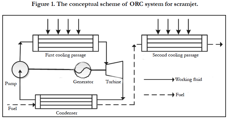
Figure 1. The conceptual scheme of ORC system for scramjet.
Part of the heat is converted to other forms of energy and the heat load of fuel coolant could be indirectly decreased. In addition, the output work of the turbine can drive the fuel pump and an electric generator to provide the power for vehicle subsystems. In summary, both cooling the engine and power generation are achieved by the ORC thermal management system onboard.
Parameters Analysis
The objective of ORC system is to decrease the heat load of fuel coolant and provide the power for the vehicle. There is a new performance parameter to compare the performance of ORC thermal management system with that of regenerative cooling system. The simplified scheme of the system is shown in Figure 2. Under the same external heating condition, it is assumed that (1) constant specific heat, (2) no pressure loss from cooling passage and heat exchanger, (3) no heat transfer loss.
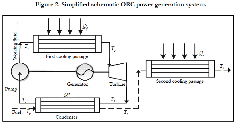
Figure 2. Simplified schematic ORC power generation system.
In order to evaluate the performance of cooling scramjet, the multiplication ratio of fuel heat sink which is described as the increase of fuel cooling capacity according to comparing ORC power generation system with regenerative cooling is defined as follows [23]:
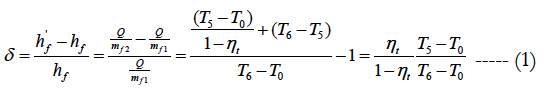
Where hf and h'f are respectively actual heat sink and "indirect" heat sink. For regenerative cooling, cooling capacity relation of fuel is Q = mf1hf, while cooling capacity relation of fuel is Q = mf2h'f for ORC thermal management system.
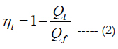
And thermal efficiency of ORC can be calculated as:
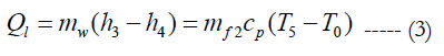
For ORC power generation system, the heat rejection of working fluid is equal to the heat absorption of fuel in condenser can be interpreted as:
The heat absorption of working fluid in evaporator can be interpreted as:

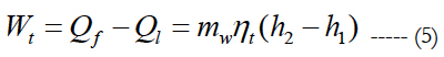
output power of ORC power generation system can be expressed as:
The parameters of an ORC system for scramjet are the multiplication ratio of fuel heat sink, the efficiency and output power.
Thermodynamic Analysis Method
As heat exchangers, turbine and pump are the key components in ORC system. The thermodynamics analysis is just an appropriate theory which has been widely used to analyze the performance of ORC for the power, efficiency and so on. Therefore, thermodynamic analysis method for ORC power generation system will be performed in the following.
The working fluids of ORC have been selected which have high critical pressure and temperature. At the same time, the selection of the working fluid for the ORC system is mainly aimed at analyzing the performance parameters. NIST (National Institute of Standards and Technology) software has been used to simulate the behavior of the working fluid. The thermodynamic properties of the selected fluid are obtained at the critical point values in terms of both pressure and temperature. Temperature-Entropy (T-S) diagram of irreversible ORC working is shown in Figure 3. 1-2-3-4-1 is the working process of cycle.
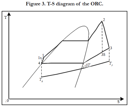
Figure 3. T-S diagram of the ORC.
1-2 is the heat absorbing process from the hot source of scramjet wall. Taking into account of the scramjet wall basically keep a high temperature, it is supposed that heat exchange performance between working fluid and scramjet wall is easy actualization. The temperature difference of heat exchanging is enough large for cooling passage. The highest temperature at the state point of 2 is lower than the temperature of working fluids chemistry labilization. 4-1 and 2-3 are irreversible compression and irreversible expansion processes, respectively. It is assumed that the condenser inlet hydrocarbon fuel coolant temperature is 300K, and the condensation temperature is higher than 320K. 3-4 is exothermic heat process to variable-temperature low temperature cold source. Supposed that the fuel coolant flow rate and the specific heat of fuel are constant, so the temperature distribution of hydrocarbon fuel coolant is about as:
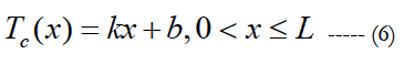
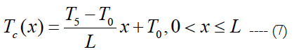
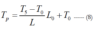
The temperature of fuel inlet is about T0 and outlet is T5. The fuel coolant of the condenser inlet is regarded as O of coordinate and the flowing path is along x. the length of the condenser fuel coolant flowing path is L, so the temperature distribution of fuel coolant is expressed as:
The condenser of ORC system is treated as counter-flow. Temperature-Enthalpy (T–H) diagram is shown in Figure 4, the heat released by the working fluid is equal to the heat absorbed by the fuel coolant. Based on Figure 4, the minimum temperature difference of heat exchange is located at the line of the working fluid saturated vapor. L0 is the Pinch Point temperature position and the Pinch Point temperature is about as:
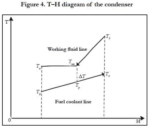
Figure 4. T–H diagram of the condenser.
If the condensation temperature gives, the temperature of fuel outlet is expressed as:
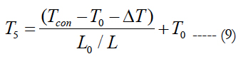
Where ΔT is the minimum temperature difference of heat exchange, which is not less than 10K.
The working fluid pressure of the condenser is Pcon by basing the saturated temperature from NIST REFPEOP 8.0 [24]. From the condenser, the rates of working fluid and fuel coolant mass flows are mw and mf, respectively, according to the relationship of the heat equilibrium in the condenser, it is expressed as:
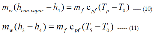
When the working fluid condensation temperature gives, the working fluid saturated vapor enthalpy is gotten and L0/L is obtained by Eq. (8), Eq. (10) and Eq. (11). And then the temperature of fuel outlet is calculated.
The performance parameters of the ORC system are calculated by Figure 5, which depicts the flow chart of the proposed method. The working fluid condensation temperature is limited by the fuel original temperature. And the working fluid chemical decomposing temperature is determined the working maximum temperature. According to the evaporation pressure, condensation temperature and the working maximum temperature, the working fluid enthalpy and entropy are obtained at state points 1, 2, 3, 4, when internal loss of turbine and pump are characterized with ηexp and ηpump, respectively. Then, the efficiency of ORC system and the condenser outlet fuel temperature are calculated. With the rate of fuel coolant flow, the rate of working fluid flow, the heat absorption at first cooling passage, the output power of ORC can be calculated. At last, the multiplication ratio of fuel heat sink would be analyzed with the known outlet temperature of fuel coolant in second cooling passage.
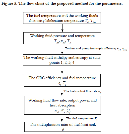
Figure 5. The flow chart of the proposed method for the parameters.
From the above analysis, condensation temperature and evaporation pressure with different working fluids have effects on the parameters of an ORC system such as the multiplication ratio of fuel heat sink, the efficiency and output power. The working maximum temperature with different working fluids is not same.
Results and Discussion
The Mach number of air stream is about 6 and the rate of fuel flow is about 0.435kg/s. The pressure of fuel in the cooling passage is under supercritical condition, the average specific heat of fuel is (dodecane is regarded as fuel). It is assumed that the turbine and pump efficiencies are 0.85 and 0.8, respectively, the condenser inlet hydrocarbon fuel coolant temperature is 300K, the temperature of fuel coolant in second passage outlet is 750K.
In the present study, the analysis is performed with different organic working fluids such as R123, R113, R141b, benzene, toluene and D4. The main properties of working fluids are shown in Table 1.
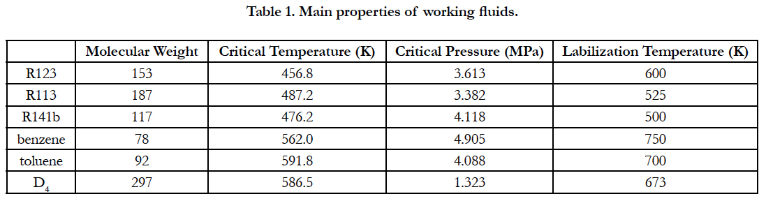

Table 1. Main properties of working fluids.
The working fluids of ORC have been selected R123, benzene and toluene which have high critical pressure and labilization temperature. It is supposed that the maximum temperatures of working fluids are 600K, 750K and 700K, respectively. The effect of the condensation temperature and evaporation pressure on the efficiency and output power, the heat absorption at first cooling passage and the multiplication ratio of fuel heat sink are studied.
Figure 6 shows the distribution of the efficiency and output power, the heat absorption at first cooling passage and the multiplication ratio of fuel heat sink utilizing R123 with different evaporator pressures and condensation temperatures. Figure 6a shows the cases of ORC system efficiency. It is considered that condensation temperature changes from 320K to 420K, evaporator pressure changes from 2MPa to 8MPa. When peva = 8MPa and Tcon = 320K, the system efficiency (20.6%) is maximum.
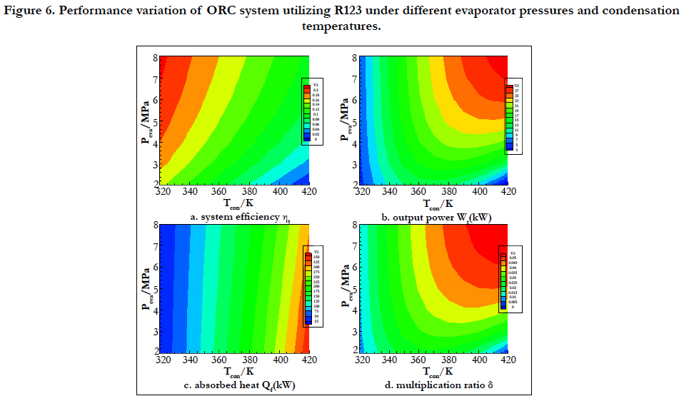
Figrue 6. Performance variation of ORC system utilizing R123 under different evaporator pressures and condensation temperatures.
Figure 6b shows variation of the ORC output power with different working parameters. As condensation temperature and evaporator pressure increase, the ORC output power increases. When peva = 8MPa and Tcon = 420K, the system output power (28.5kW) is maximum. Figure 6c shows variation of the ORC heat absorption at first cooling passage. When peva = 2MPa and Tcon = 420K, the system heat absorption (346.4kW) is maximum. Figure 6d shows variation of the multiplication ratio of fuel heat sink. When peva = 8MPa and Tcon = 420K, the multiplication ratio of fuel heat sink (0.0559) is maximum.
The system performance parameters have the same variation utilizing different working fluids with different evaporator pressures and condensation temperatures. Figure 7 shows the system performance parameters variation utilizing benzene. The system maximum efficiency is 25.9% when peva = 8MPa and Tcon = 320K in Figure 7a. The system maximum output power and the multiplication ratio of fuel heat sink are 54.7kW and 0.1075, respectively, when peva = 8MPa and Tcon = 450K in Fig. 7b and Figure 7d. The system maximum heat absorption is 471.9kW when peva = 2MPa and Tcon = 450K in Figure 7c.
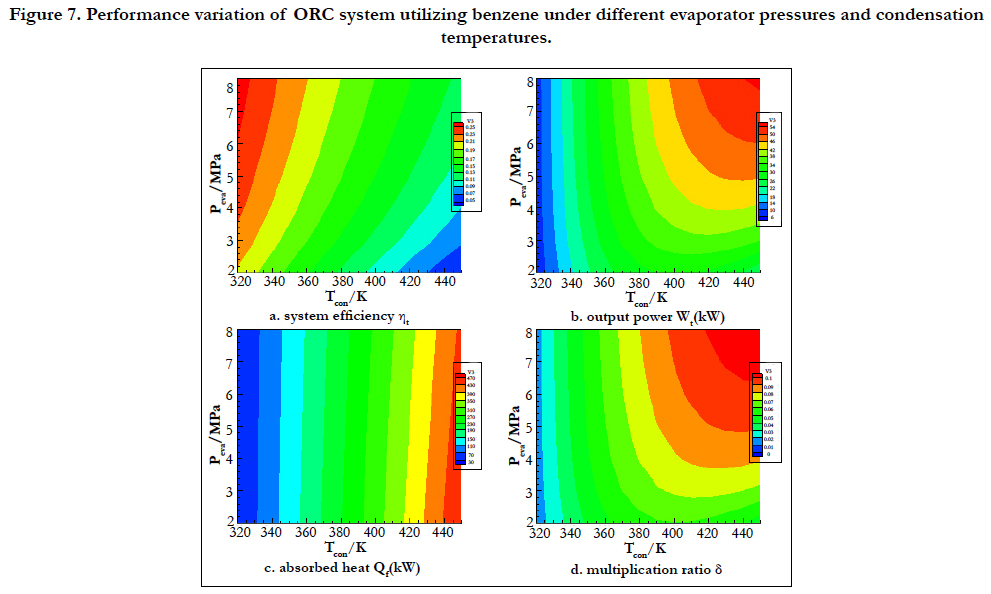
Figure 7. Performance variation of ORC system utilizing benzene under different evaporator pressures and condensation temperatures.
Figure 8 shows the system performance parameters variation utilizing toluene. The system maximum efficiency is 26.3% in Figure 8a. The system maximum output power and the multiplication ratio of fuel heat sink are 49.9kW and 0.0978, respectively in Figure 8b and Figure 8d. The system maximum heat absorption is 412.5kW in Figure 8c.
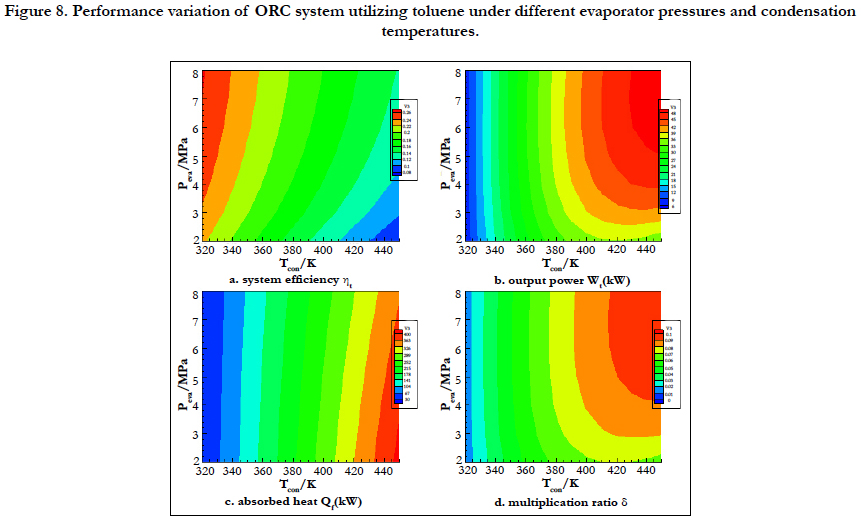
Figure 8. Performance variation of ORC system utilizing toluene under different evaporator pressures and condensation temperatures.
From the variety of analysis discussed above, the ORC system for thermal absorption and recovery is applied for cooling scramjet. The value of performance parameters can be obtained with different fluids under some assumption. It is assumed that (1) the turbine and pump efficiencies are 0.85 and 0.8, respectively, (2) the cycle pressure ratio is not too high, (3) the minimum temperature difference of heat exchange is not less than 10K, (4) the minimum efficiency of the system is not less than 15%, (5) the ORC system heat absorption is larger than that of fuel absorbing at second cooling passage. From the above assumptions, benzene and toluene as working fluids can meet the request, the working and performance parameters are shown in Table 2.
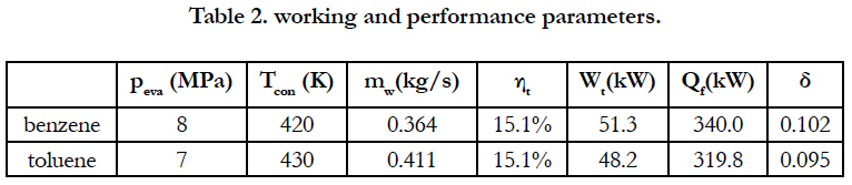
Table 2. working and performance parameters.
From the variety of analysis discussed above, the value of the multiplication ratio of fuel heat sink can reach 10 percent and the output power of ORC system is about 50kW. The ORC system also produces electric power and the output power is about 50kW, which can be utilized for the fuel feeding subsystem and power generation subsystem.
Conclusion
A physical model of the ORC system is constructed for recovering the scramjet cooling heat, and the performance parameters of the system are discussed. The thermodynamic analys is method for the system is depicted which is a guidance for analyzing the ORC system for cooling scramjet. According to such analysis, benzene and toluene as working fluids can be used for the ORC system under some assumptions. The efficiency, output power and the multiplication ratio of fuel heat sink are 15.1%, 51.3kW and 0.102, respectively utilizing benzene under evaporator pressure (8MPa) and condensation temperature (420K). Utilizing toluene as working fluid, the efficiency, output power and the multiplication ratio of fuel heat sink are 15.1%, 48.2kW and 0.095, respectively under evaporator pressure (7MPa) and condensation temperature (430K). There is some output power for hypersonic vehicle obtained from the ORC power generation system, which indicates the potential value lying in the application of this system.
References
- Chang JT, Bao W, Yu D, Fan Y, Shen Y, Zhou W. Hypersonic inlet control with pulse periodic energy addition. J Aerospace Eng. 2009 Feb 1;223(2):85- 94.
- Mahapatra D, Jagadeesh G. Shock tunnel studies on cowl/ramp shock interactions in a generic scramjet inlet. J Aerospace Eng. 2008 Aug 1;222(8):1183-91.
- Kontis K. Flow control effectiveness of jets, strakes, and flares at hypersonic speeds. J Aerospace Eng. 2008 May 1;222(5):585-603.
- Thompson T, Weeks D, Walker S, Anttonen J. DARPA/USAF Falcon Program Update on the SpaceX Maiden Launch, Mishap Investigation and Return to Flight. In AIAA SPACE 2007 Conference & Exposition; 2007. p. 9912.
- Bao W, Qin J, Yu D. Integrated thermal management method of energy based on Closed Brayton Cycle for scramjet. In 42nd AIAA/ASME/SAE/ASEE Joint Propulsion Conference & Exhibit; 2006. p. 4685.
- Carpenter C, Verma S, Kapat JS. Numerical study of enhancement of regenerative cooling using ribs. In49th AIAA/ASME/SAE/ASEE Joint Propulsion Conference; 2013. p. 3996.
- Gascoin N, Gillard P, Dufour E, Touré Y. Validation of transient cooling modeling for hypersonic application. J Thermophys Heat Tr. 2007 Jan;21(1):86-94.
- Chang J, Bao W, Yu D, Fan Y, Shen Y. Effects of wall cooling on performance parameters of hypersonic inlets. Acta Astronaut. 2009 Aug 1;65(3-4):467- 76.
- Tsujikawa Y, Northam GB. Effects of hydrogen active cooling on scramjet engine performance. Int J Hydrogen Energ. 1996 Apr 1;21(4):299-304.
- Huang H, Spadaccini LJ, Sobel DR. Fuel-cooled thermal management for advanced aeroengines. J Eng Gas Turb Power Trans ASME. 2004 Apr 1;126(2):284-93.
- Qin J, Bao W, Zhou W, Yu D. Performance cycle analysis of an open cooling cycle for a scramjet. J Aerospace Eng. 2009 Jun 1;223(6):599-607.
- Bao W, Qin J, Zhou W, Yu D. Parametric performance analysis of multiple re-cooled cycle for hydrogen fueled scramjet. Int J Hydrogen Energ. 2009 Sep 1;34(17):7334-41.
- Bao W, Qin J, Zhou W, Zhang D, Yu D. Power generation and heat sink improvement characteristics of recooling cycle for thermal cracked hydrocarbon fueled scramjet. Sci China Technol Sci. 2011 Apr 1;54(4):955-63.
- Bao W, Zhang D, Qin J, Zhou W. Performance analysis on fuel turbo-pump and motor system of scramjet engine. In10th International Energy Conversion Engineering Conference; 2012. p. 4159.
- Quoilin S, Van Den Broek M, Declaye S, Dewallef P, Lemort V. Technoeconomic survey of Organic Rankine Cycle (ORC) systems. J Renew Sustain Energy. 2013 Jun 1;22:168-86.
- Qiu G, Shao Y, Li J, Liu H, Riffat SB. Experimental investigation of a biomass-fired ORC-based micro-CHP for domestic applications. Fuel. 2012 Jun 1;96:374-82.
- Aneke M, Agnew B, Underwood C, Wu H, Masheiti S. Power generation from waste heat in a food processing application. Appl Therm Eng. 2012 Apr 1;36:171-80.
- Nihous GC. A preliminary assessment of ocean thermal energy conversion resources. J Energy Resour Technol. 2007 Mar 1;129(1):10-7.
- Kaşka Ö. Energy and exergy analysis of an organic Rankine for power generation from waste heat recovery in steel industry. Energy Convers Manag. 2014 Jan 1;77:108-17.
- Liu X, Wang X, Zhang C. Sensitivity analysis of system parameters on the performance of the Organic Rankine Cycle system for binary-cycle geothermal power plants. Appl Therm Eng. 2014 Oct 5;71(1):175-83.
- Carcasci C, Ferraro R, Miliotti E. Thermodynamic analysis of an organic Rankine cycle for waste heat recovery from gas turbines. Energy. 2014 Feb 1;65:91-100.
- Miller EW, Hendricks TJ, Peterson RB. Modeling energy recovery using thermoelectric conversion integrated with an organic Rankine bottoming cycle. J Electron Mater. 2009 Jul 1;38(7):1206-13.
- Qin J, Zhou W, Bao W, Yu D. Thermodynamic analysis and parametric study of a closed Brayton cycle thermal management system for scramjet. Int J Hydrog Energy. 2010 Jan 1;35(1):356-64.
- Rayegan R, Tao YX. A procedure to select working fluids for Solar Organic Rankine Cycles (ORCs). Renew Energ. 2011 Feb 1;36(2):659-70.