Stress Analysis of Rotating Composite Solid Disc
Alemayehu Adde Y*
Space Engineering Research & Development Directorate, Ethiopian Space Science & technology Institute, Addis Ababa, Ethiopia.
*Corresponding Author
Yeshurun Alemayehu Adde (Kibret), PhD,
Space Engineering Research & Development Directorate,
Ethiopian Space Science & technology Institute, Addis Ababa, Ethiopia.
Tel: +251928992614
Email: kibret10@gmail.com
Received: May 15, 2019; Accepted: August 27, 2019; Published: August 28, 2019
Citation:Alemayehu Adde Y. Stress Analysis of Rotating Composite Solid Disc. Int J Aeronautics Aerospace Res. 2019;6(4):205-209. doi: dx.doi.org/10.19070/2470-4415-1900025
Copyright: Alemayehu Adde Y© 2019. This is an open-access article distributed under the terms of the Creative Commons Attribution License, which permits unrestricted use, distribution and reproduction in any medium, provided the original author and source are credited.
Abstract
There are numerous applications of rotating disc in the aerospace industry such as in gas turbines. There are many causes of disc failure. Among them, maximum tensile and bending stresses induced under the action of centrifugal forces are the main causes of disc failure. In this work, the evaluation of stresses in an E-glass epoxy material rotating solid disc is studied using finite element method. The FE model is developed by using ABAQUS software for analysis and the maximum principal stress is determined for different angular velocities. The analysis of stresses within the disc of constant thickness and density is based on the maximum principal stress criterion and its associated flow rule. It is observed that when increasing the angular velocity of the disc, the stress quadratically increasing. The result also shows that crack initiates at the center of the composite disc radially at a certain minimum speed.
2.General Ter
3.Introduction
4.Stress Analysis of a Rotating Composite Solid Disc
5.Geometric Dimension of Solid Disc
6.Material Properties of Solid Disk
7.Results and Discussion
7.1 Subsections
7.2 Discussion
8.References
Keywords
Composite Material; Rotating Disc; Stress Analysis.
General Terms
Stress Analysis.
Introduction
Stress analysis is the complete and comprehensive study of stress distribution in the specimen under study. To improve the quality of the product and in order to have safe and reliable design, it is necessary to investigate the stresses induced in the component during working condition.
Rotating discs are historically of interest to designers due to their vast spectrum of use in the aerospace industry. Gas turbine discs are an important example of such applications. In gas turbines, rotating discs are simultaneously subjected to mechanical and thermal loads. A disc may be under internal pressure due to shrink fit on its mounting shaft; in addition an external load is applied to its outer edge resulting from the blade effects installed on its outer periphery. In operation, when the disc rotates with significant angular velocity due to the hot gases passing through the blades, which create a variable temperature field on the disc. This study devoted to analyze the mechanism of damage of the turbine disc and also to determine the critical high stresses due to excessive rotational speeds [1].
As the rise of the concern for reducing the weight of aerospace products increases, while not compromising its strength, it is found that composite materials are the perfect choice. Composite materials are then the dominant solution for such a requirement as a result of ability to tailor material properties upon desire.
Generally, composite discs can be categorized into two types based on geometry, i.e. rim discs and solid discs. A rim disc is an annular wheel, which concentrates the rotor mass as much as possible in the relatively thin rim in order to increase the mass moment of inertia around the rotating axis. It can easily be built with the filament-winding technique and has a good advantage of exploiting the high unidirectional strength of fiber to withstand the major stress in the circumferential direction. The radial stress for composite rim discs is usually low and therefore, can be sustained by the transverse strength of the composite. In contrast, a rotating disc looks like the flat round plate centrally connected to driving shaft. It has more mass moment of inertia around the rotating axis than a composite rim discl when consuming the same swept area. It is designed to reach higher values of the energy density with higher peripheral velocities in comparison with a rim-type rotor. However, the state of stresses in the disc is more complicated due to the emergence of comparatively higher radial stress. Furthermore, if the disc is made from a laminated orthotropic layer, the interfacial stresses causing delamination may be important and partially control the failure of the disc.
This, consequently, influences the more complex failure modes of the composite disc. At the beginning of composite study study, a number of different discs have been identified and published by some researchers [1-5], Moreover, a recent review by [6] indicated lots of research and publications on composite discs during a couple of past decades. This leads to a significant growing in using and developing composite discs in engineering applications. To additionally stream in this demand, this paper will present another mean of analysis of composite solid discs. The main objective is to develop a fairly simple but favorably realistic model to predict composite disc stress behaviors during operation, particularly damage in the disc that is capable of being generated at a high rotating speed and the highest possible speed the disc can sustain right before crack initiation. Moreover, the model developed can be used to aid an investigation of disc failure mechanism and to complement as a design criteria of a composite solid disc.
Stress Analysis of a Rotating Composite Solid Disc
All material on each page should fit within a rectangle of 18 x.
As mentioned above, the state of stresses that could happen in a laminated composite disc is quite complicated. A three-dimensional model is the most appropriate to govern the real physical behavior of the rotating disc. Nonetheless, for the sake of simplicity it is better to assume that if the laminated disc is thin when compared to its diameter, the classical lamination theory is applicable and then the problem is now classified as a plane stress problem. Additionally, delamination can be neglected for preliminary analysis purpose. Moreover, if the stacking sequence is made such that the quasi-isotropy is achieved, then in overall, the disc behaves very much like an isotropic material, which provides material axisymmetric besides the geometrical symmetry around the rotating axis. According to the assumptions stated earlier, the effective material properties for quasi-isotropic symmetric laminate in a composite disc can be expressed as [7]:
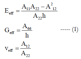
where Eeff, Geff and veff are effective Young’s modulus, effective shear modulus, and effective Poisson’ ratio of the laminate, respectively, h the total thickness of the laminate. Aij, when i,j = 1,2,6, are in-plane stiffness of each lamina and related to reduced stiffness as follows:
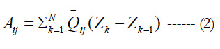
In the above, N is the total number of ply in the laminate, Qij are the transformed reduced stiffness and are defined by:
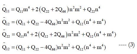
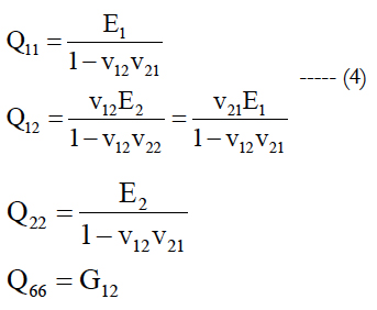
where m = cosα , n = sinα, in which α is the angle between the global coordinate system X-Y and fiber direction (or 1-axis) of composite disc at a given layer depicted in Figure 1. The Qij, as expressed in Equation (iii), are reduced stiffness and are functions of the engineering constants as shown in Equation (iv).
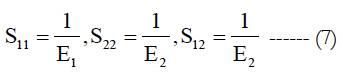
E1 and E2 denoted in Equation (iv) are in-plane extensional modulus of the composite material along the fiber and transverse to the fiber directions, respectively. The property G12 is in-plane shear modulus. In addition, v12 and v21 are major and minor Poisson’s ratios, respectively.
In addition, one can utilize the elasticity solution of an isotropic rotating disc derived in [8, 9] for the quasi-isotropic case. The state of stresses at a material point reads:
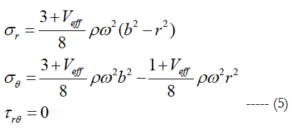
In the above, σr is effective radial normal stress in the whole composite solid disc, σθ effective circumferential normal stress, τrθ effective in-plane shear stress, ρ the mass density, ω the angular velocity of the disc, b the radius of the disc, and r radial distance from rotating axis.
It can be observed that normal stresses in the rotating disc are always positive or in tension as indicated by Equation (5). Therefore, in accordance with the conditions set above, failure at a material point in the composite solid disc will occurs if at least one of the following equations of failure surface envelope satisfied.
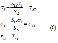
In the above, Sij when i,j = 1,2,6 are compliances of the composite material defined in Equation (vi). σXT, σYT and τXY are ultimate tensile strengths in the 1 and 2 directions, and ultimate shear strength in the 1-2 plane, respectively.
Satisfaction of the first or second expression of Equation (vii) indicates the failure in tension is in-the-fiber direction or perpendicular- to-fiber direction, respectively. However, if the third expression satisfies, the failure occurs in shear mode in the 1-2plane.
The set of the aforementioned equations can basically determine the maximum rotating speed of the composite disc. This maximum rotating speed is defined as the speed that causes damage in at least one of the failure modes in every lamina throughout the whole disc. According to Equation (5), it is expected that the damage initially occurs at the center of the disc and subsequently spread to the outer radius of the disc when the rotating speed gets higher. The maximum speed obtained from this approach provides fundamental information with respect to failure mechanism. However, it may be significantly overestimated due to negligence of damage accumulation within the solid disc before the damage spreading.
Geometric Dimension of Solid Disc
The major dimensions of the disc under consideration for the present analysis are as follows:
Outer Diameter of Solid Disc (Do) = 1.1m
Inner Diameter of Solid Disc (Di) =0.1m
Thickness of the Solid Disc (t) = 0.025m
Material Properties of Solid Disk
The laminated disc used in the analysis is made of E-glass Epoxy material of which properties are tabulated as given in Table 1 [10]. The ply thickness is 3.125mm and its stacking sequence is [0/-45/45/90]s with totally 8 plies.
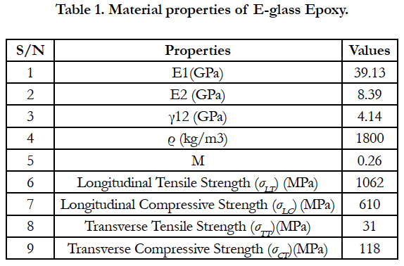

Table 1. Material properties of E-glass Epoxy.
The computational results show that the dominant failure mode of the laminated solid disc made from E-glass epoxy material is matrix cracking. Amongst all the solutions obtained from equation (11), the second equation yields the lowest failure angular speed at almost every position on the discs since this equation shows the stress is in a perpendicular to fiber direction. The results show that the matrix cracking initiates at the center of the composite disc through the disc thickness at a certain speed. Then the damage propagates along the radius of the disc when the angular velocity keeps increasing as anticipated, since the magnitudes of radial and hoop stresses both are highest at the center point and start decaying when moving away from the rotating axis.
The first angular velocity that creates the central point crack (defining herein as first-failure spinning speed or FFSS) is 4608rad/ sec for E-glass epoxy.
Also, at any running speed higher than FFSS the accumulated damage region with in the solid disc forms elliptical shape on the 1-2 plane in each layer as shown in Figure 1.
The elliptical shape has the 1- axis as a major axis and 2- axis as minor axis. This elliptical damage zone has the same shape in all laminate. Additionally, the elliptical damage zone in each lamina can be union altogether approximately to form a cylindrical damage volume (CVD) inside the composite damage volume (CVD) inside the composite discs as depicted in Figure 1. Furthermore, the maximum rotating speed in this case will be specified as the speed at which the CDV is equal to the whole disc volume.
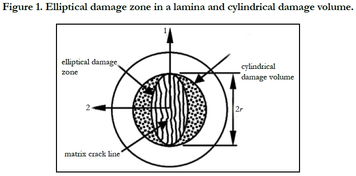
Figure 1. Elliptical damage zone in a lamina and cylindrical damage volume.
Figure 2 shows the stress (maximum principal stress) distribution of the whole solid dics FE model. Also, shows the stress distribution along the radial distance of the disc from its inner edge. Here the speed is below FFSS.
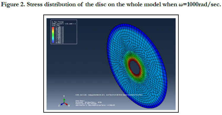
Figure 2. Stress distribution of the disc on the whole model when ω=1000rad/sec.
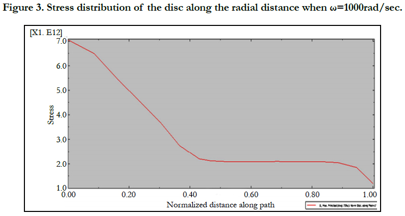
Figure 3. Stress distribution of the disc along the radial distance when ω=1000rad/sec.
Figure 4 the stress (maximum principal stress) distribution of the whole solid disc FE model. Also Figure 5 shows the variation stress along the radial distance of the disc from its inner edge. Here the angular speed is above FFSS (about 10000rad/sec).
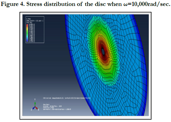
Figure 4. Stress distribution of the disc when ω=10,000rad/sec.
From Figure 2 and Figure 3 one can see that there is a high stress is observed around the inner hole of the solid disc. Consequently, crack initiation is observed around these areas when increasing the angular speed of the solid disc. From Figure 4 we can observe that there is a high distortion of inner regions. It shows that crack initiation occurred and hence deformation the disc has already started. Also it is observed that the FFSS is 4608rad/sec. The maximum stress at this speed is 15.06x10⁴ GPa.
The result found from ABAQUS (FE) confirms with the theory that, the maximum stress in a rotating composite solid disc is at the center of the solid disc.
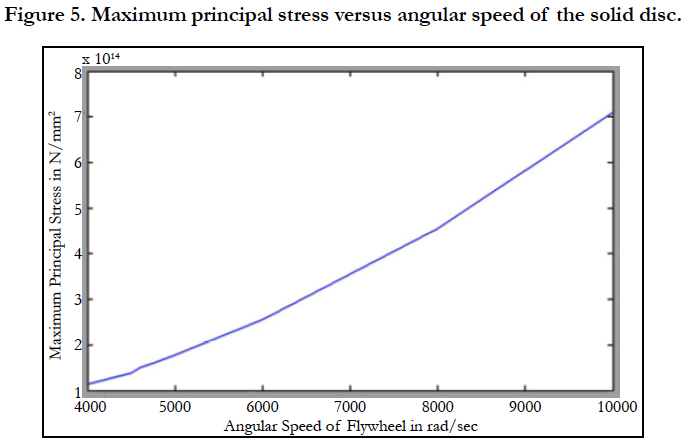
Figure 5. Maximum principal stress versus angular speed of the solid disc.
References
- Witek L. Failure analysis of turbine disc of an aero engine. Engineering failure analysis. 2006 Jan 1; 13(1):9-17.
- Bowman M, Debray SK, Peterson LL. Reasoning about naming systems. ACM Transactions on Programming Languages and Systems (TOPLAS). 1993 Nov 1;15(5):795-825.
- Ding W, Marchionini G. A study on video browsing strategies. 1998 Oct 15.
- Fröhlich B, Plate J. The cubic mouse: a new device for three-dimensional input. InProceedings of the SIGCHI conference on Human Factors in Computing Systems 2000 Apr 1: 526-531.
- Tavel P. Modeling and Simulation Design. AK Peters Ltd. 2007.
- Sannella MJ. Constraint satisfaction and debugging for interactive user interfaces (Doctoral dissertation, University of Washington). 1994.
- Forman G. An extensive empirical study of feature selection metrics for text classification. Journal of machine learning research. 2003; 3(Mar):1289-305.
- Brown LD, Hua H, Gao C. A widget framework for augmented interaction in SCAPE. InProceedings of the 16th annual ACM symposium on User interface software and technology 2003 Nov 2; 1-10.
- Yu YT, Lau MF. A comparison of MC/DC, MUMCUT and several other coverage criteria for logical decisions. Journal of Systems and Software. 2006; 79(5):577-90.
- Spector AZ. Achieving application requirements. In Distributed systems 1990 Apr 1 (pp. 19-33).