Design of Electric Underwater Vehicle Engine: Efficient No-fuel Consuming Substitute for Marine Diesel Engine
Majumder SD*
Institute of Engineering and Management, Kolkata, India.
*Corresponding Author
Samarpan Deb Majumder,
Institute of Engineering and Management, Kolkata, India.
Tel: 8240656601
E-mail: debsamarpanmajumder@gmail.com
Received: December 22, 2018; Accepted: December 14, 2019; Published: December 23, 2019
Citation: Majumder SD. Design of Electric Underwater Vehicle Engine: Efficient No-fuel Consuming Substitute for Marine Diesel Engine. Int J Marine Sci Ocean Technol. 2019;6(1):103-109. doi: dx.doi.org/10.19070/2577-4395-1900014
Copyright: Majumder SD© 2019. This is an open-access article distributed under the terms of the Creative Commons Attribution License, which permits unrestricted use, distribution and reproduction in any medium, provided the original author and source are credited.
Abstract
An efficient passive no-fuel consuming underwater propelling vehicle engine operating only on electricity has been developed and studied in this research. The engine is housing a propeller fan, a compressive body housing a 75KWh rechargeable battery pack, 4 pole 3 phase Induction motor, inverter and a single speed transmission 9.73:1 gearbox connected to the driving shaft which in turn drives the turbine at the outlet. The turbine being coaxially connected to the motor acts like a generator generating around 69KW during braking of vehicle through regenerative braking which is in turn used to charge the battery pack. The power thus generated by the motor is transmitted to the shaft producing around 5990 RPM, accounting all losses. The theory and concept are derived from the working principle of a scramjet engine, air breathing engine and an Electric Vehicle. The velocity achieved by the vehicle catering all losses and drag at its peak working condition is calculated around 66.87 m/sec, almost double to that of the speed of conventional underwater running vehicles. Demonstrates Design of Engine; Demonstrates Design Calculations; Demonstrates output parameters of Engine.
2.Introduction
2.1 Nomenclature
2.2 Rear and Front view of the Electric Underwater Propelling Engine
2.3 Compressive Body
2.4 Properties of Alloy C-276
3.Equations
4.Calculations
4.1 Pressure Ratio
4.2 Electric Engine Specifications
4.3 Clearance Dimension
4.4 Angle of Attack for Maximum Velocity
4.5 Design of Propeller, Compressive Body and Turbine
4.6 Mechanical Engine Specifications
5.Stress and Flow Analysis
6.Design Material and Cost Analysis
7.Conclusion
Keywords
Underwater; Passive; Engine; Inverter; Motor; Scramjet.
Introduction
In accordance with the proposal, electricity without any dependency on gasoline is used as the driving source for propelling the vehicle. Electricity here is produced by a Battery which drives the 4 pole 3 phase induction motor to propel the vehicle under water. At the standstill condition, electricity from the lithium ion battery is first converted from DC to AC with the help of an inverter. The AC supply is fed into the motor which employs its rotor to drive the propeller fan at the front of the vehicle at an average speed of 5990 RPM. A Single Speed transmission or a gear box is installed in between the motor and inverter so as to use the power of the motor to drive the propeller and turbine axially mounted on the same shaft. The vehicle propelling underwater would not require any friction braking to slow down the vehicle. Hence, cutting off the supply or releasing the acceleration pedal would suffice. (Figure 1)
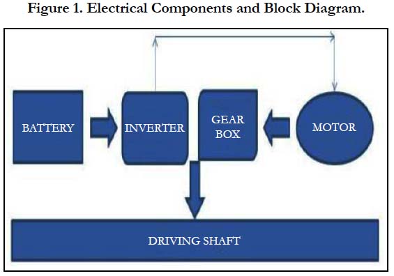
Figure 1. Electrical Components and Block Diagram.
The engine is ducted with a certain degree of angle inwards so as to reduce the formation of vortex leading to turbulence at the inlet. The ducting not only improves the performance of the fan blades but also aids in producing additional thrust. The primary design has been inspired from a scramjet engine, but with a turbine at the outlet to further increase the kinetic energy of the liquid passing through. The solid body between the propeller blade and turbine houses the electrical power hub. The diverging converging body in between the propeller and turbine acts as an efficient and a passive compressive device similar to the one used in a scramjet or ramjet engine. The inlet has been installed as diverging so as to optimise supersonic compression and an increase in velocity across the engine. Furthermore, a diverging inlet will maintain a considerably lower inlet to outlet temperature ratio. The cooling of the engine will be achieved passively with the help of water flowing within the engine. The electric housing shall be cooled using a cross flow shell and tube heat exchanger with water as the coolant. (Figure 2)
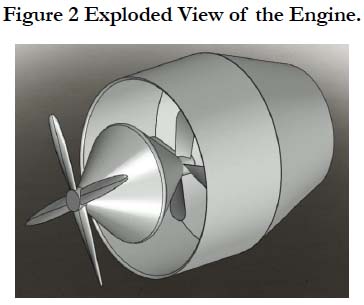
Figure 2. Exploded View of the Engine.
The turbine at the exit upon deceleration will enable the motor to act as a generator thus using the wasted kinetic energy or torque to recharge the battery. Upon full running conditions and depletion of battery charge, the vehicle needs to recharge itself in recharging stations. The average time taken to recharge a battery completely shall be around 1 hour. The duty time for a lithium ion battery on full continuous running condition shall be around 20 to 25 hours. Additionally with a higher output power to mass ratio of the engine around 2.7, the operating efficiency increases by 24.45% from 34.65% to 59.1%. The engine housing shall be installed below the vehicle so as to ensure that the centre of gravity always acts below the buoyancy force (lower the centre of gravity, better is the stability of the body underwater). The casing of the hub is converging, thus compelling the engine to act like a nozzle too. The engine will be installed below the vehicle thus pushing the centre of gravity even lower so as to maintain stability underwater. The design of propeller and turbine blades has been achieved on the basis of standard values of angle of attack so as to cater to the drag loss. The taper angle of the compressive body has been accounted on the basis of the increase in velocity of the fluid passing through. (Figure 3)
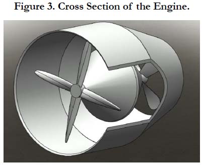
Figure 3. Cross Section of the Engine.
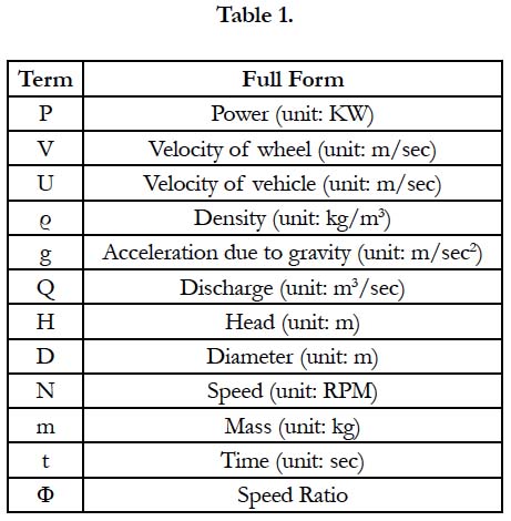

Table 1.
The design is completed in Solid Works accounting all the standard values for dimensions of Propeller, Turbine Blades, Compressive Body and Shaft as well as the clearance areas of all the sections. The unit of dimensions are considered to be in millimetres and the scale has been set to 1:1. (Figure 4)
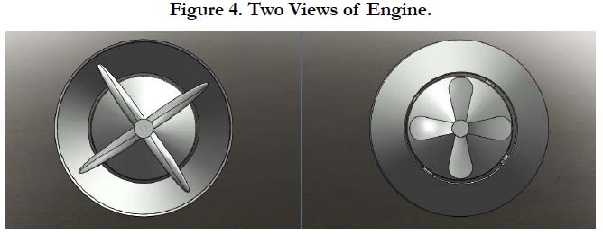
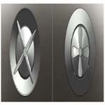
Figure 4. Two Views of Engine.
The compressive body at the mid-section of the engine is installed for serving two major purposes:
• Produce ram effect (similar to scramjet engine) to increase the velocity of flow at the outlet of engine.
• House the electrical components like Battery, Inverter, Induction Motor and Single Speed Gear Transmission Box.
This component shall be bolted to the outer casing of the engine, i.e., a duct. For high structural rigidity, high tensile strength, and high compressive strength and to undermine cavitation and corrosion, Alloy C-276 shall be used for its construction. The use of this material will also lengthen the lifetime of the component thus entailing lower running and maintenance cost. (Figure 5)
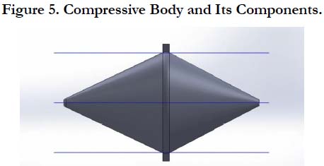
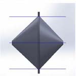
Figure 5. Compressive Body and Its Components.
Corrosion Material’s C276 is a solid-solution strengthened, nickelmolybdenum-chromium alloy with a small amount of tungsten, which exhibits excellent corrosion resistance in an assortment of harsh environments. Applications include and are not limited to, stack liners, ducts, dampers, scrubbers, stack-gas re-heaters, heat exchangers, reaction vessels and evaporators. Industries where C276 can be utilized are petrochemical and chemical processing, power generation, pharmaceutical, pulp and paper production and waste treatment to name a few. C276 is known as the most universally corrosion resistant material available today. It is used in a variety of environments from moderately oxidizing to strong reducing conditions. The limiting factor when dealing with strong oxidizing environments is the low Cr content, which means that hot, concentrated nitric acid environments are not desirable. Although, C276 has exceptional resistance to sulphuric acid and hydrochloric acid, acid chlorides, solvents, formic and acetic acids, acetic anhydride, wet chloride gas, hypo chlorites and chlorine solutions. Also, it has excellent resistance to phosphoric acid at all temperatures below boiling and at concentrations lower than 65%. Alloy C276 has excellent resistance to pitting, stress corrosion cracking and to oxidizing atmospheres. C276 also exhibits excellent resistance to corrosion by seawater especially under crevice conditions, which induce attack in other commonly used materials. (Table 2).
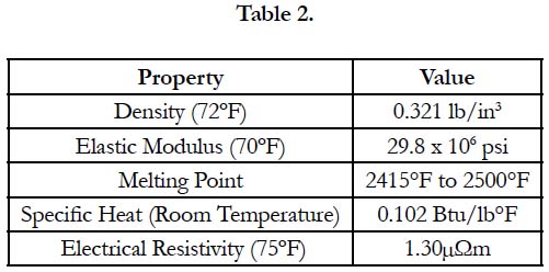
Table 2.
Being stable at higher temperatures, the coefficient of thermal conductivity is comparatively low. The material will therefore, not dissipate any unwanted heat into the ambient water thus imposing lower threat to aquatic life sensible to change in temperature. (Table 3).
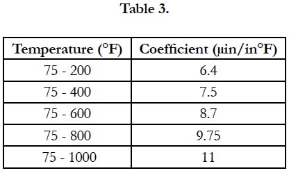
Table 3.
C276 can be formed using various cold and hot working processes. Although C276 tends to work harden it can be cold formed using the more aggressive methods such as deep-drawing, press forming or punching. Hot forming should be performed within a temperature range between 1600°F and 2250°F (870°C-1230°C) with heavier sections heated to a minimum of 2000°F before forming. Annealing of the material after working is advised and should be performed at a temperature between 2050°F and 2150°F followed by a rapid quench in a protective atmosphere or in an agitated reducing quench bath. To obtain a reducing media, add 2% (by volume) of either ethyl or propyl alcohol to water.
Equations
The standard equations of Fluid Mechanics have been followed in devising the velocity of vehicle, drag coefficient, design of the engine and studying the characteristics of the flow through turbine at the inlet and propellers at the outlet.
a. P = (ρ × g × q × h)/1000
b. V = φ√(2 × g × h)
c. m/t = ρ × a × V
d. u = π * D * N/60
e. a1v1 = a2v2 = a3v3 = av = Constant
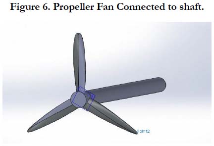
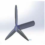
Figure 6. Propeller Fan Connected to shaft.
Calculations
Design calculations such as Pressure Ratio, Electric Engine Specification, Clearance, Angle of Attack, Propeller Blade, Turbine Blade, Compressive Body and Mechanical Component specifications have been thoroughly devised so as to enable a proper design of engine considering all criteria of design failures.
Pressure ratio acts as an integral part of increasing velocity across a component during its running condition. Higher the pressure ratio, more is the pressure developed across and therefore higher velocity is achieved. (Table 4)
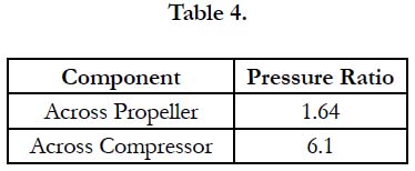
Table 4.
The heart of the engine driving the propeller and the turbine is the electrical housing. A few standard values of the engine such as the battery life, battery range and the charging time has been derived from the specification of Tesla Model S. (Table 5)
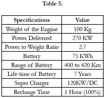
Table 5.
Clearance dimensions have been devised solely on the basis of design calculations and to cater hydraulic losses underwater that shall lead to the deterioration of the engine efficiency. (Table 6)
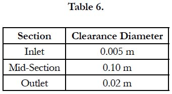
Table 6.
Optimum angle of attack has been devised so as to reduce the drag and cavitation factor with increasing velocity. (Table 7)
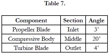
Table 7.
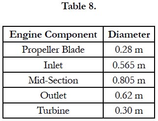
Table 8.
Mechanical Engine design calculations have been devised with the sole purpose for reducing the cost, increasing the velocity and reducing the overall drag of the engine. (Table 9) (Figure 7)
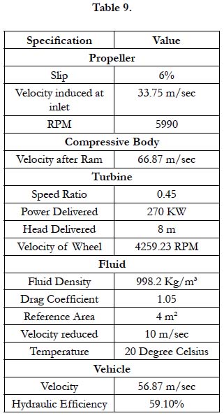
Table 9.
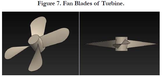
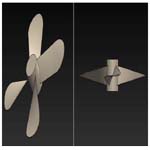
Figure 7. Fan Blades of Turbine.
Stress and Flow Analysis
The flow and stress analysis has been demonstrated and performed on Solid Works. The Stress Analysis was performed for the turbine blade which is subjected to a total Torque of 430.65 N-m. The results devised depicts that the material is well within the safety zone from fracture of the material. The results for turbine and propeller yielded the same results as the total torque would be same as they are connected co-axially to the same shaft. With the flow analysis, it has been inferred that by neglecting all hydraulic losses, the highest velocity the engine can achieve is around 96.7 m/sec. However, taking consideration of vehicle weight, hydraulic losses and friction, the velocity attained by the vehicle shall be close to 60 m/sec. (Figure 8, 9)
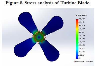
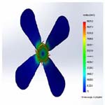
Figure 8. Stress analysis of Turbine Blade.
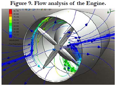
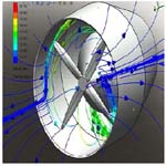
Figure 9. Flow analysis of the Engine.
Design Material and Cost Analysis
To make the engine cost effective and efficient, materials with high fatigue life as well as high structural rigidity has to be chosen. Thus, different components of the engine subjected to continuous tensile, compressive, shear and fatigue demand different materials for its construction which are listed below. (Table 10)
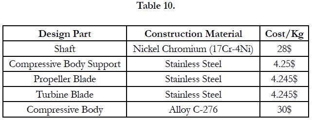
Table 10.
Conclusion
The present situation of resources depleting calls for an innovation that will eradicate the dependence of transport running on fuel. The purpose of the research is to address this problem and to suggest a no-fuel consuming electric vehicle that will efficiently serve short range operations ranging from 300 to 400 Km. The short range applications can be many, for example, it can be used as a military vehicle, can be used as an underwater environment friendly commercial transport, can be used as an alternative to clear off sea wastes in a short amount of time and can serve a crucial role in the cold chain industry by reducing the time gap between storage of food products and distribution in market thereby reducing post-harvest losses.